Create & Test
This page details the creation and testing of our device. Since we have worked on different concepts, the document is divided according to the three sprints.
!!!info Concept & Design To get more context, we would recommend reading the concept & design page first. To get a better idea behind the concepts which are realized on this page.
Sprint 1
Prototype assembly
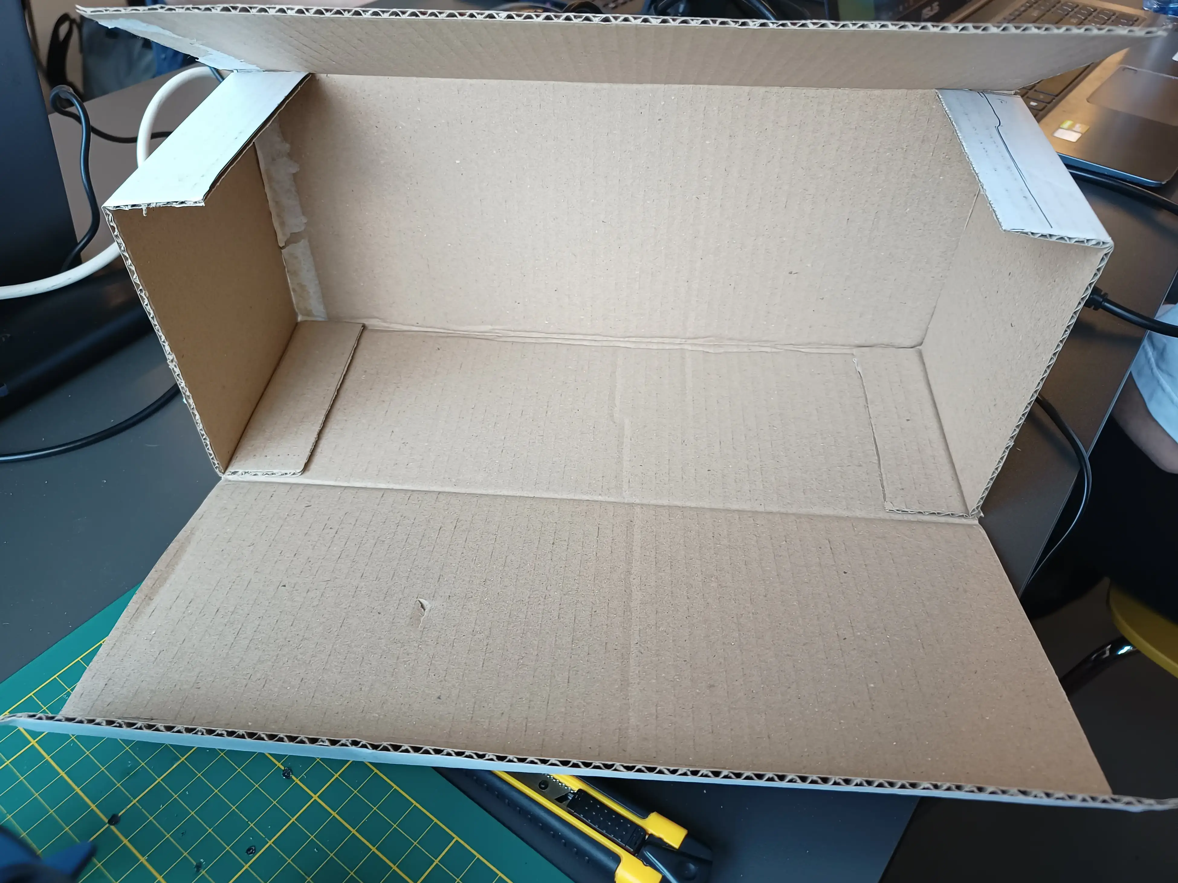
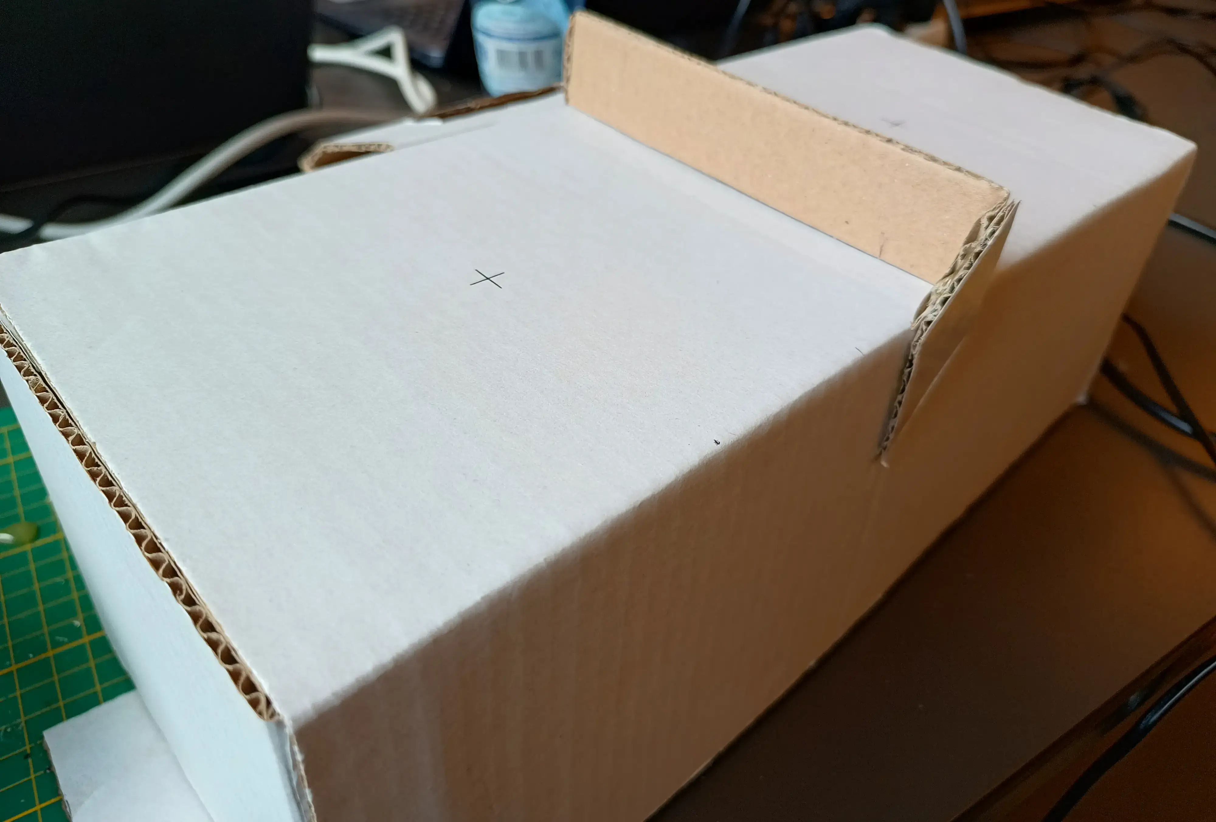
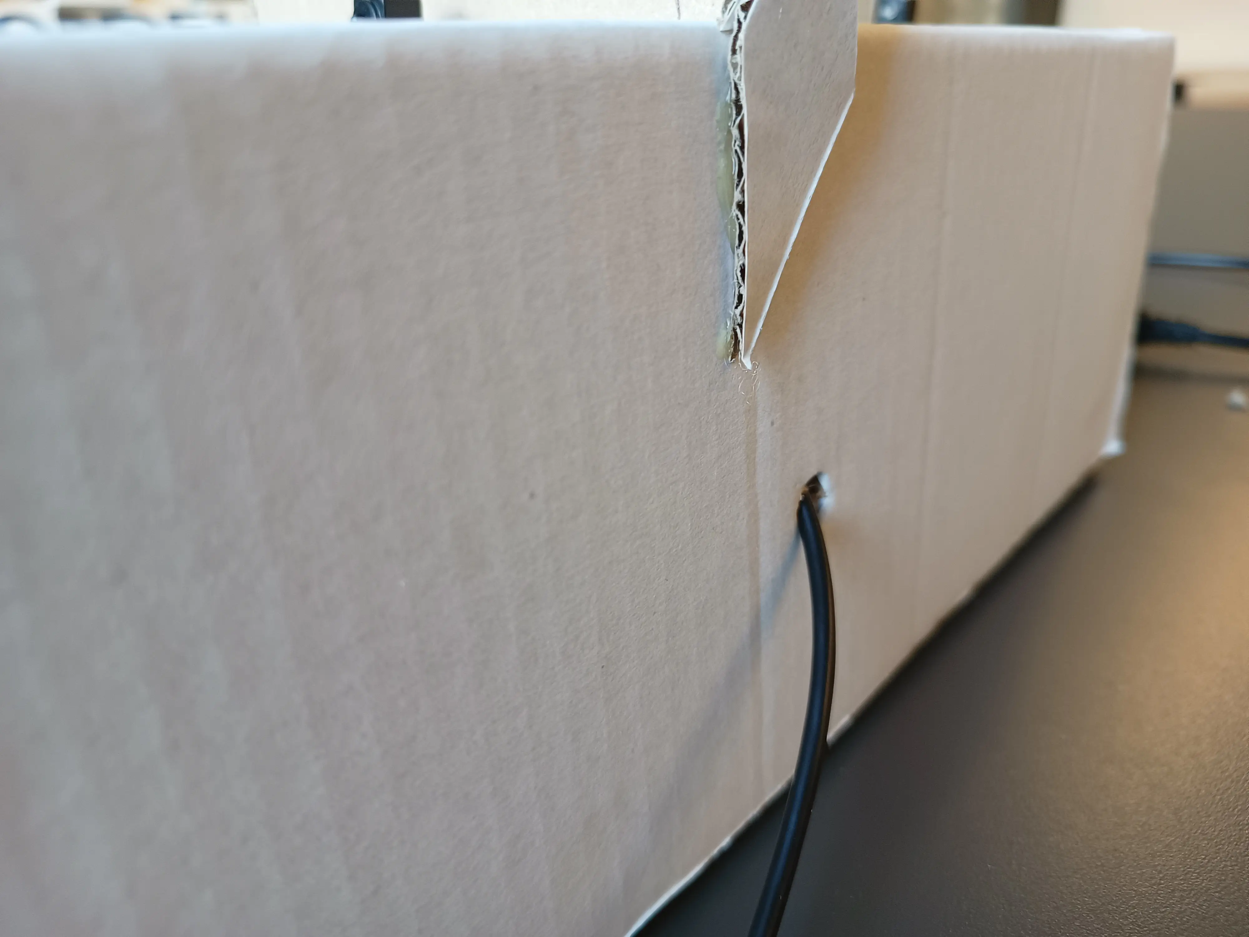
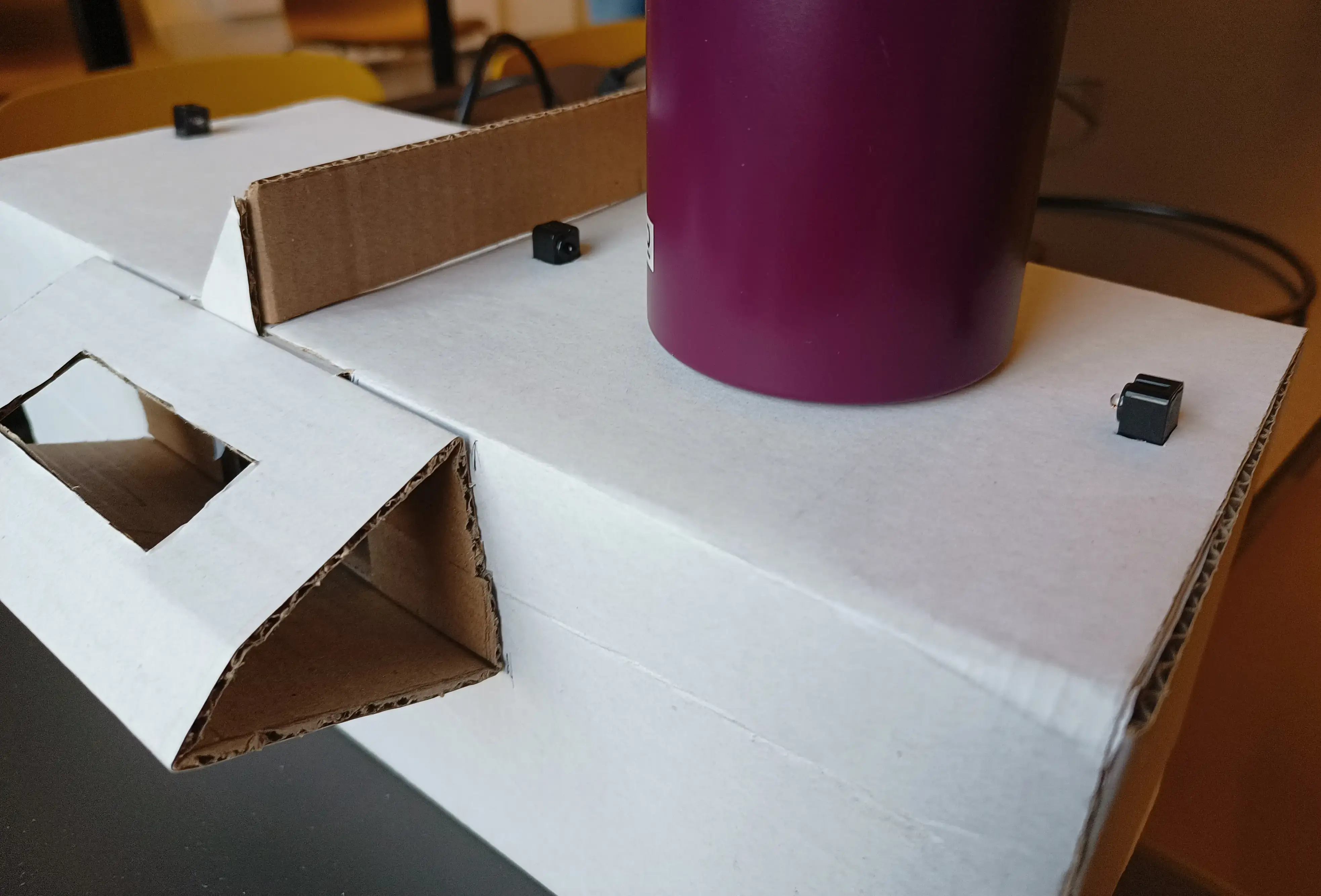
The box was created using cardboard using a box knife and some measuring. Outer shell was measured and cut into shape with cuts where bends should be percent. All bends are in line with the cardboard it's inner waves. Later assembled at the HvA with a glue gun.
When assembled like shown below this can take quite some weight. At least being able to support the 2 required cups.
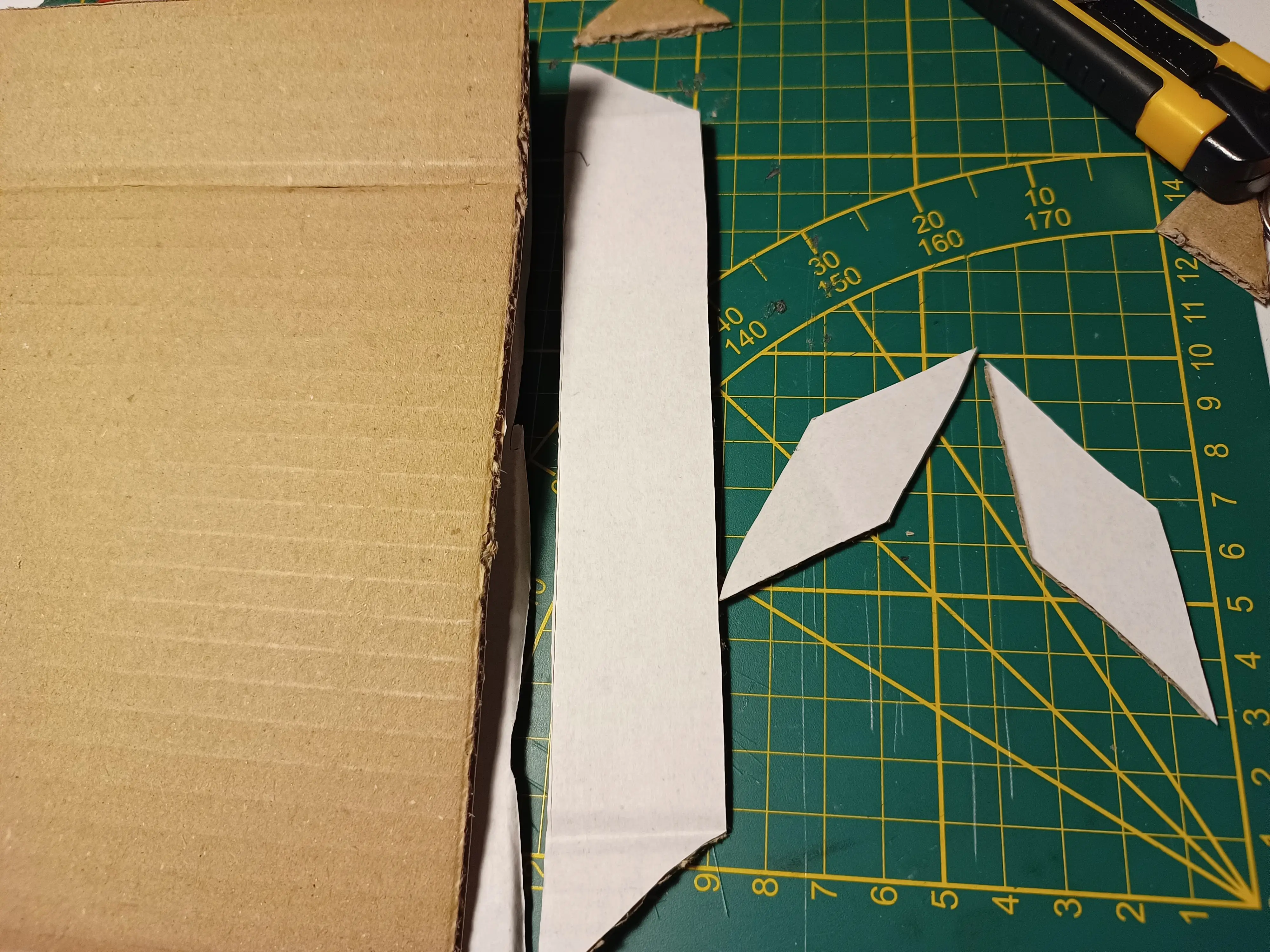
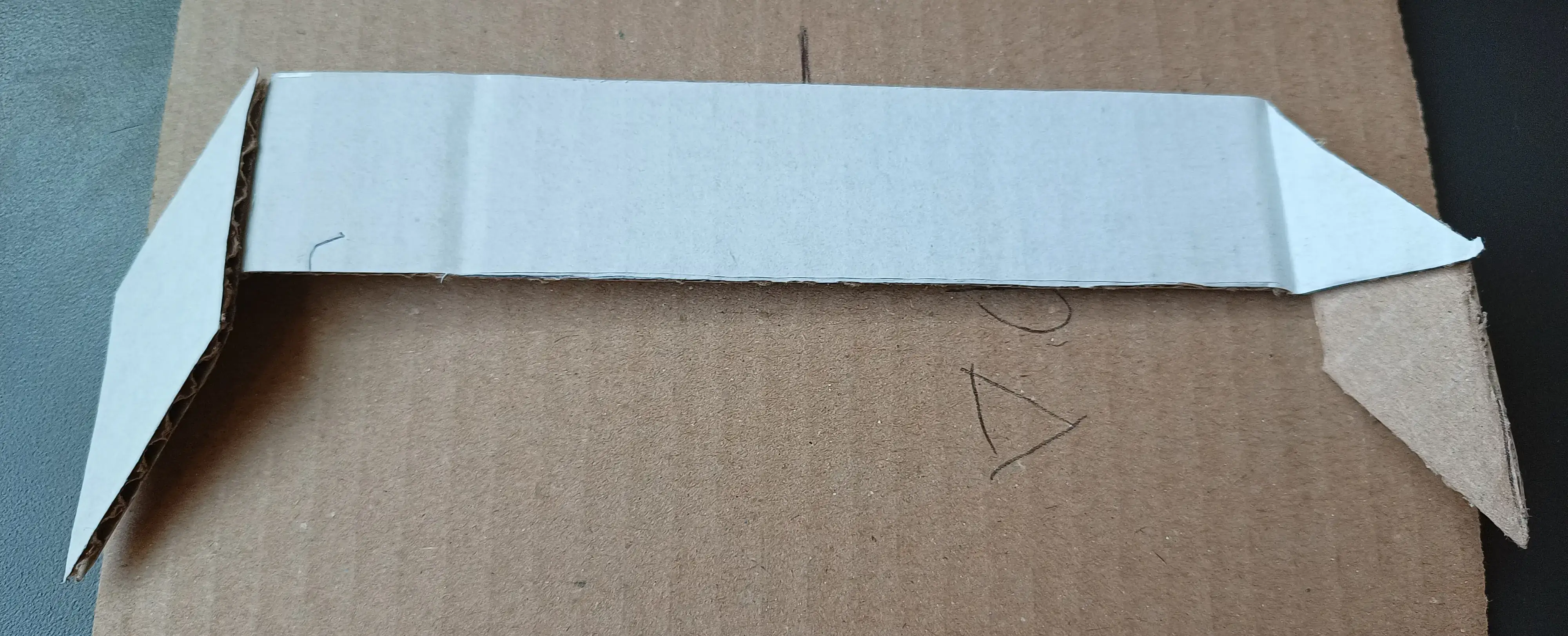
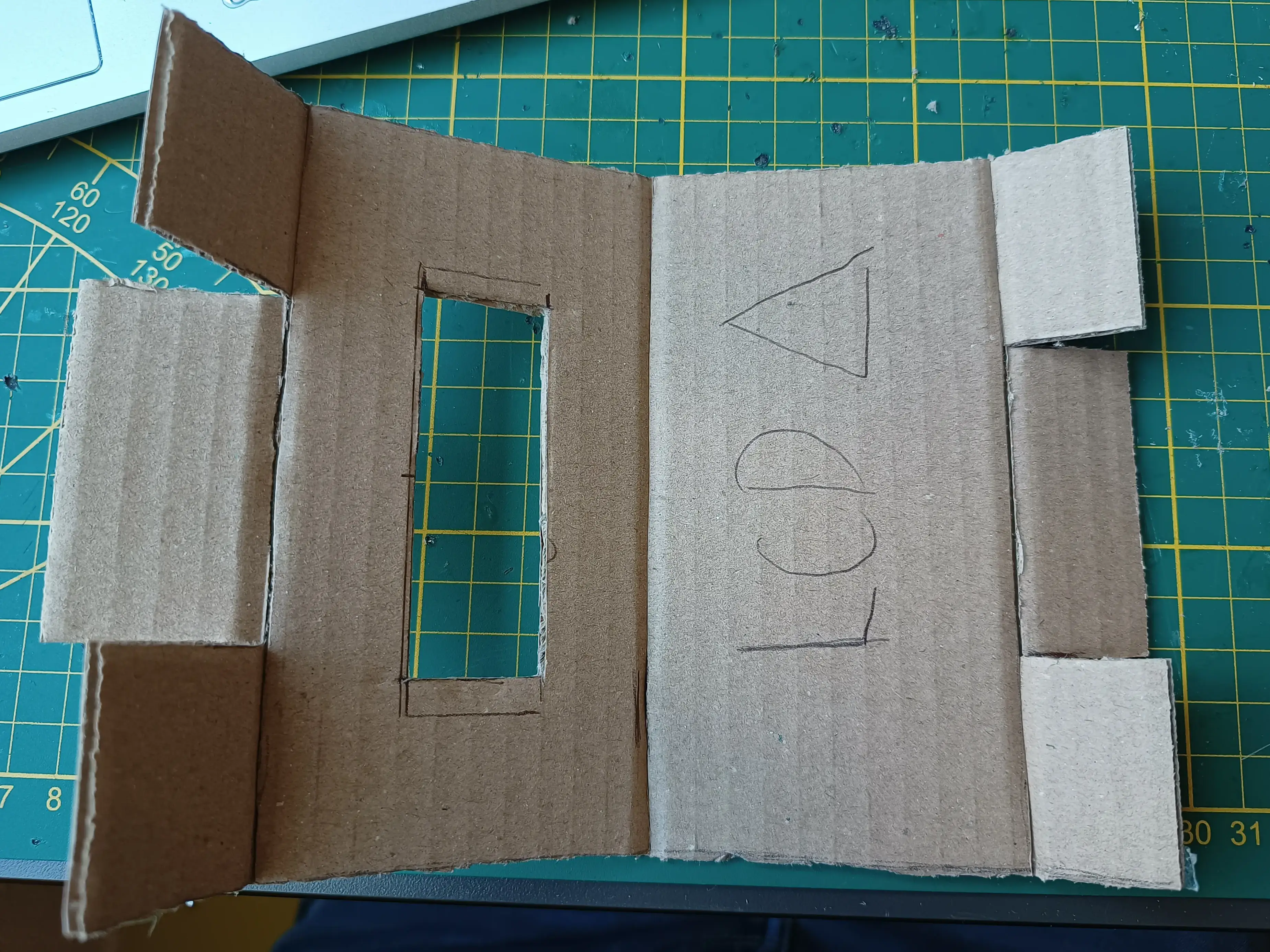
The in sketch shown separator is created with slanted corners. This with the reason that it looks better when some parts are angled at the side when securing it. With the "flaps" it can be attached more securely.
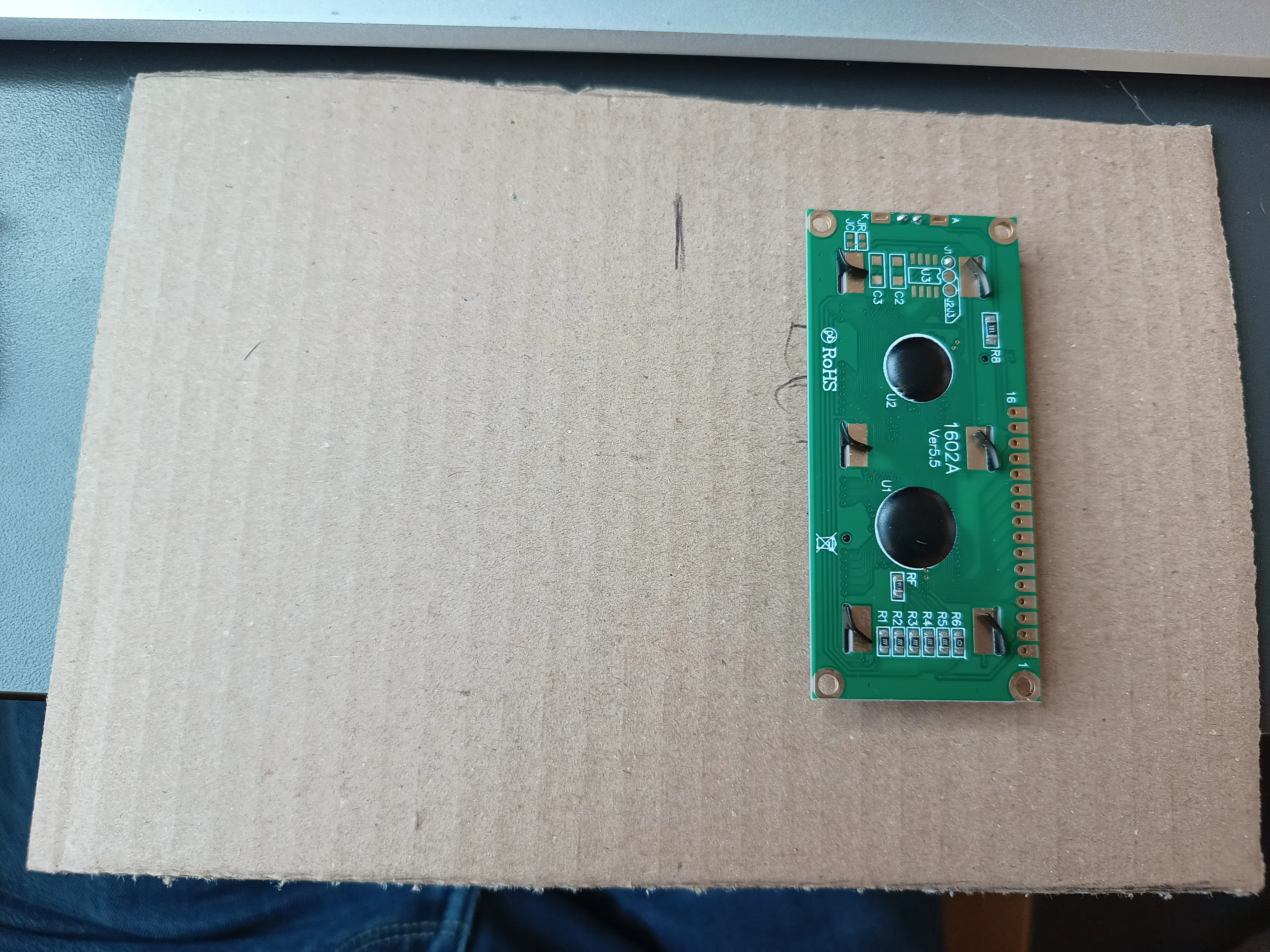
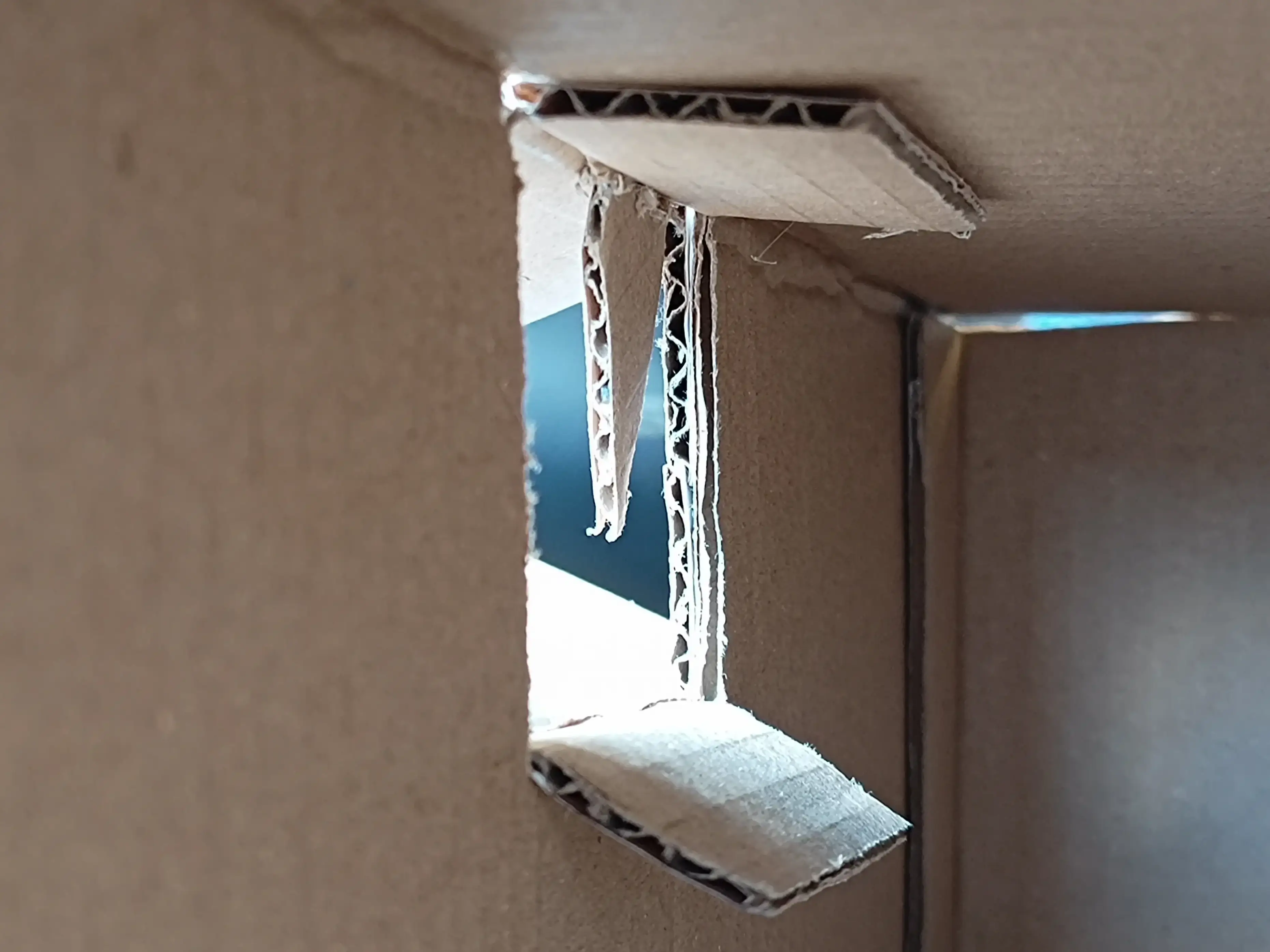
The LCD itself will be attached with a triangle for a more readable compared to the sketch. Making that required measuring the LCD and modifying the cardboard.
After which it was installed with the outer flaps folded to the center of the triangle. However the inner flaps where inserted into the main box body where a gap was.
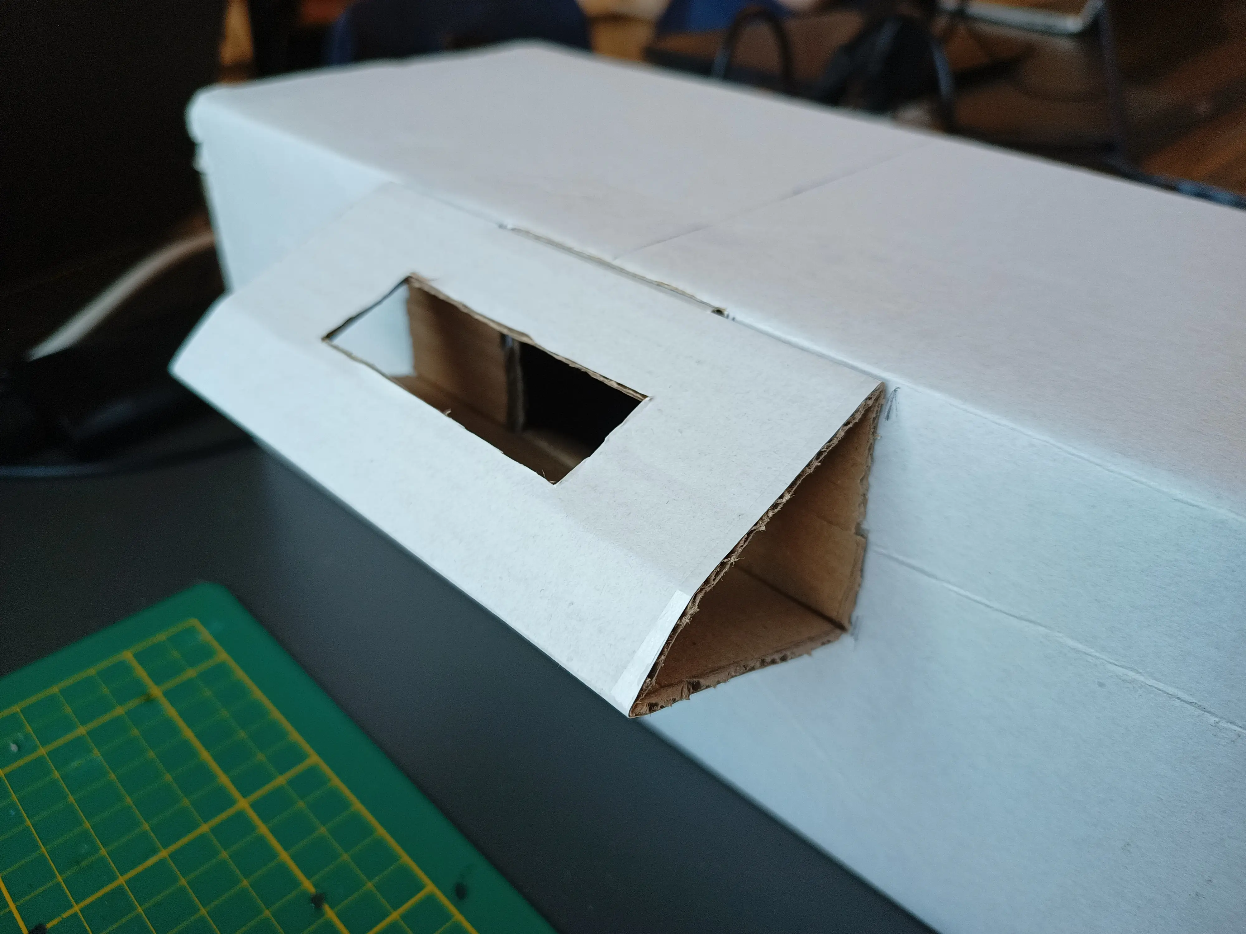
Finally everything can be mounted inside to allow for testing of the device! At least when you don't forget to plug the cable in that is.
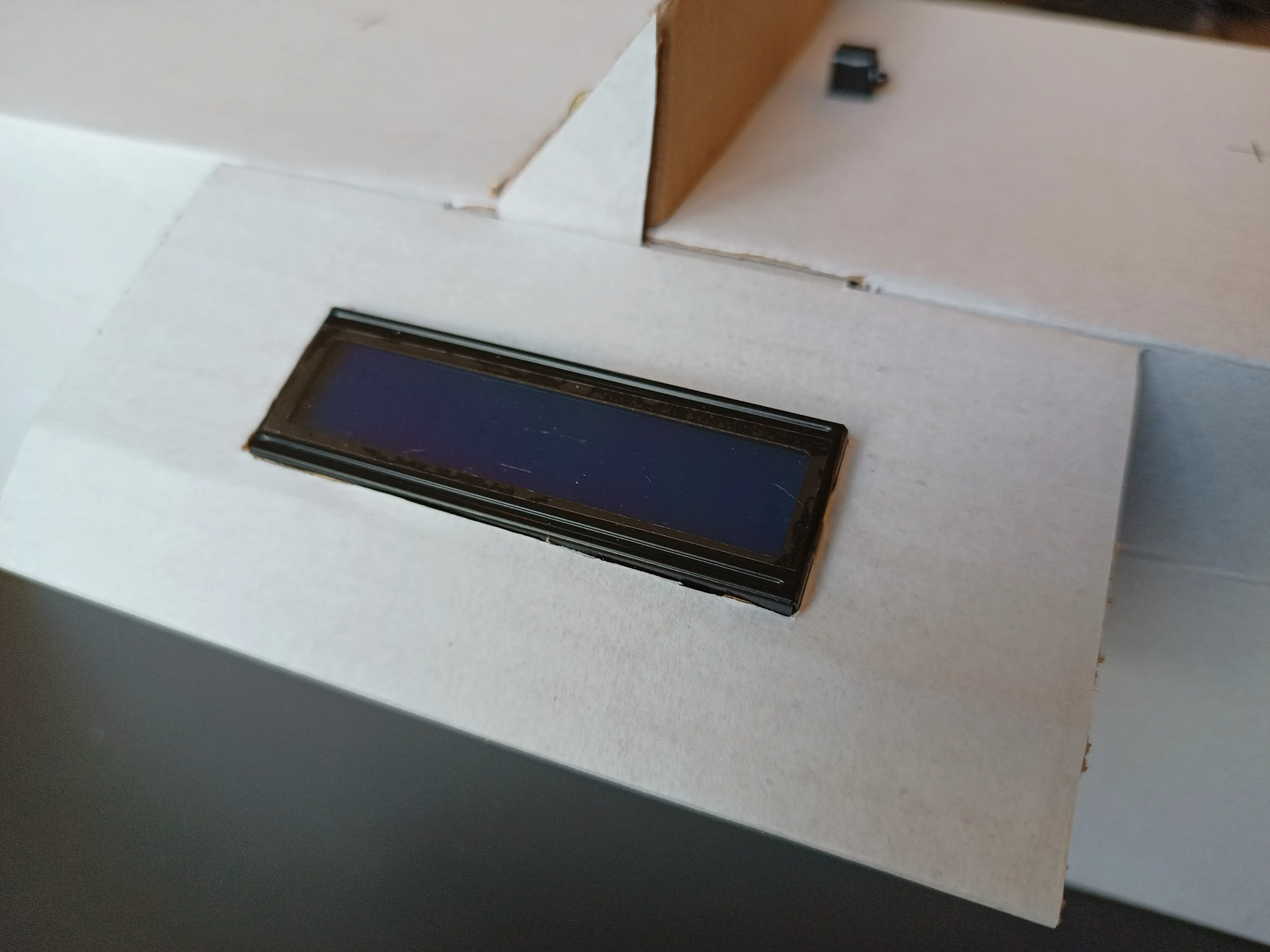
It seemed like it the device works like this in this new shell too!
The next step was to print out the specific Sustainable Development Goal images, which we have attached on the prototype design.
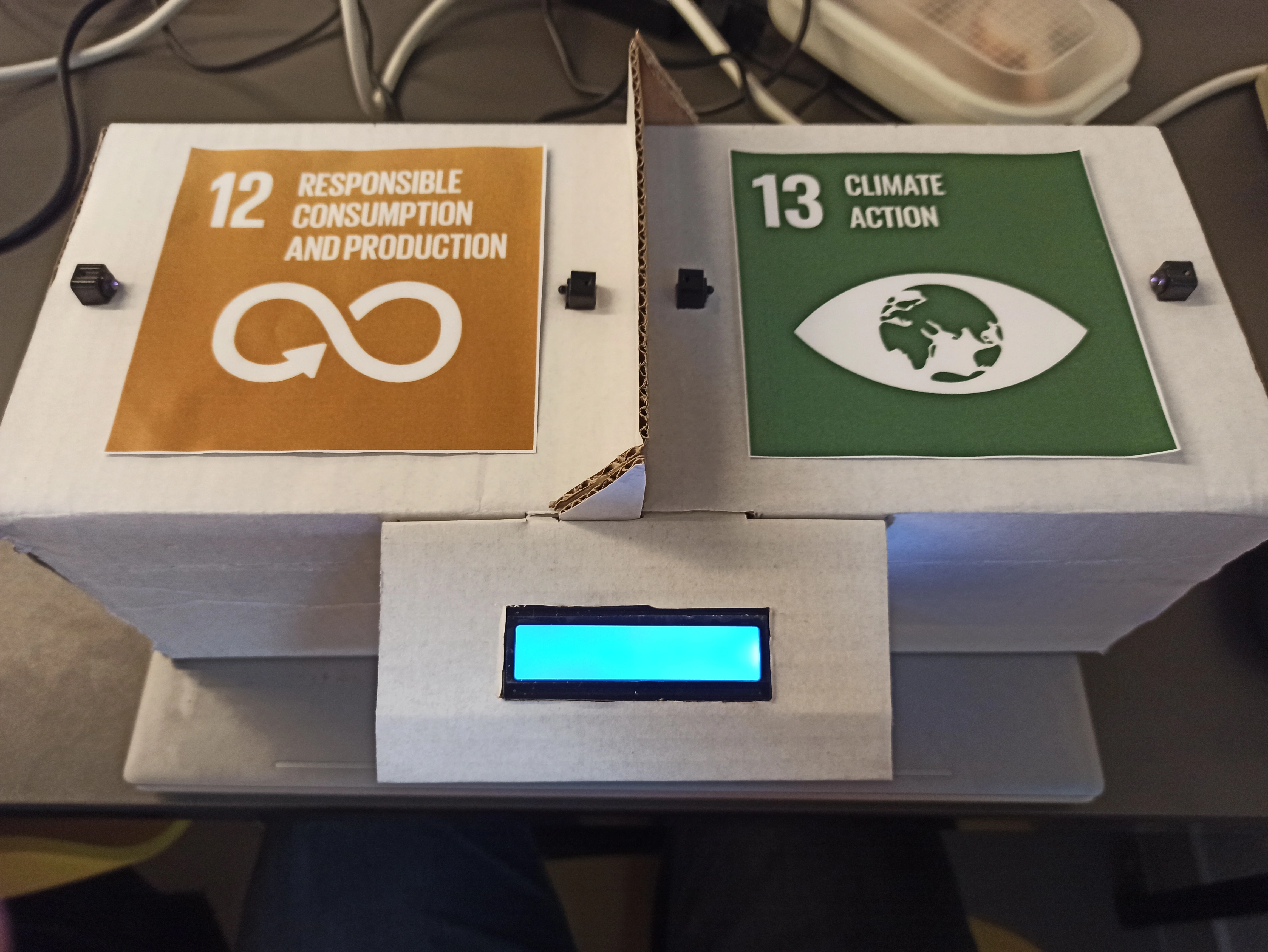
When a cup is removed, it now displays a message on the LCD, which is a fact about sustainability.
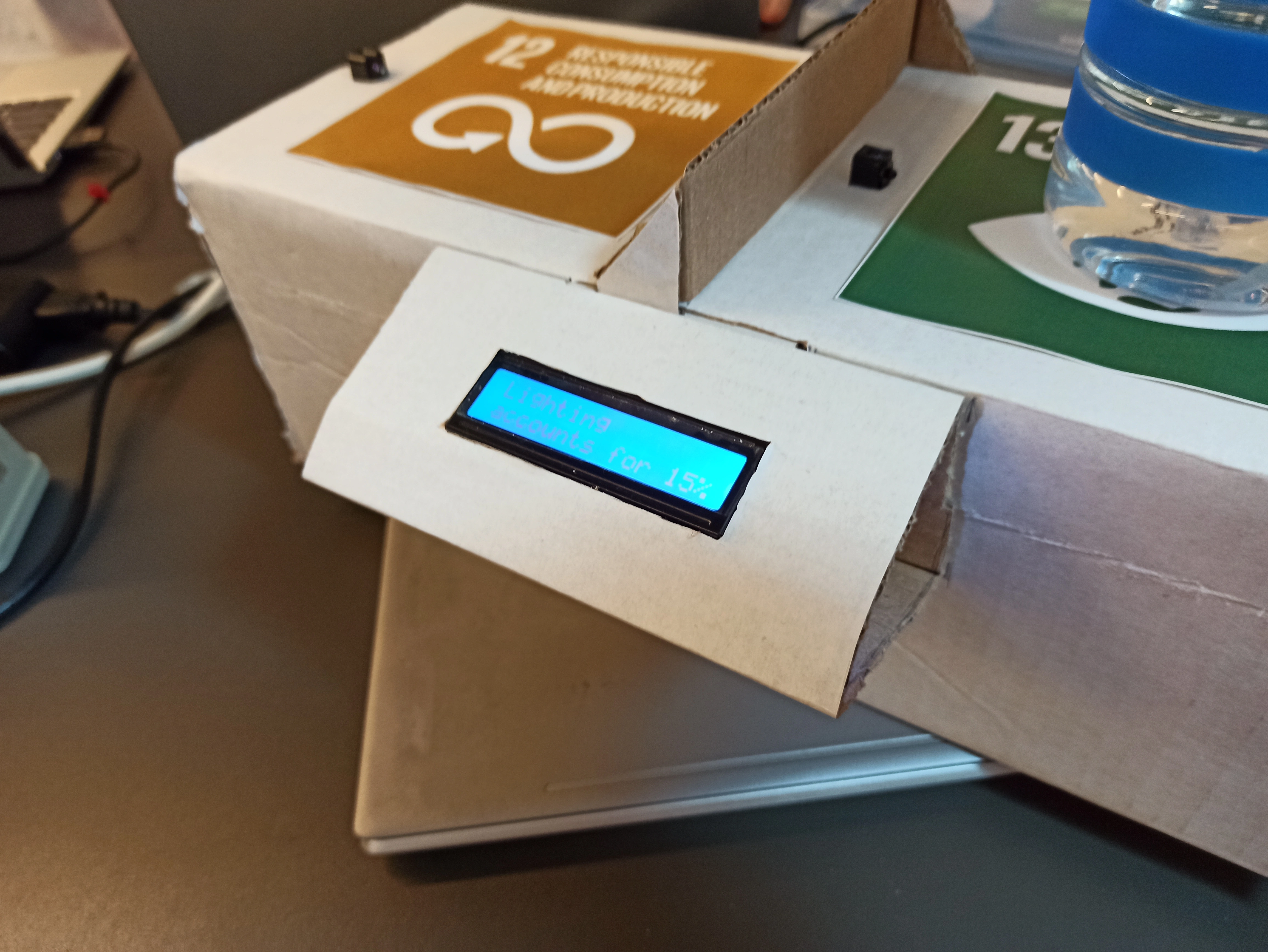
The whole finished sprint 1 prototype, with cups on top, looks like this:

Sprint 2
3D letters
To create the letter V in a 3D design we make use of the programs Tinkercad and Cura Ultimaker.The design process was done with Tinkercad because it makes it easier to make slight adjustments to the design. The design when finished looked like the following:
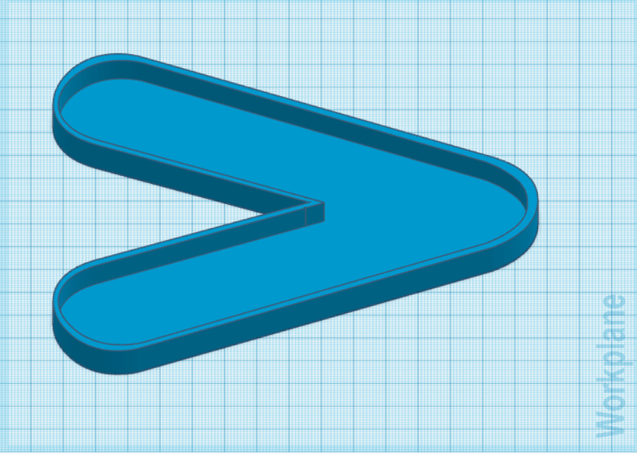
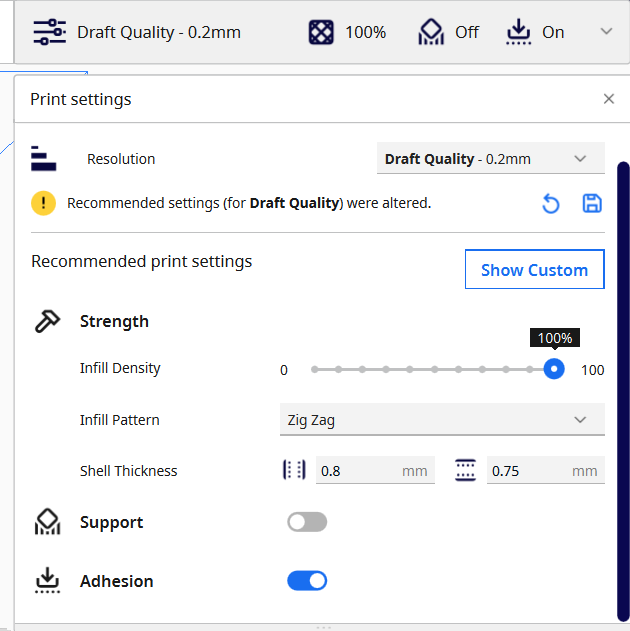
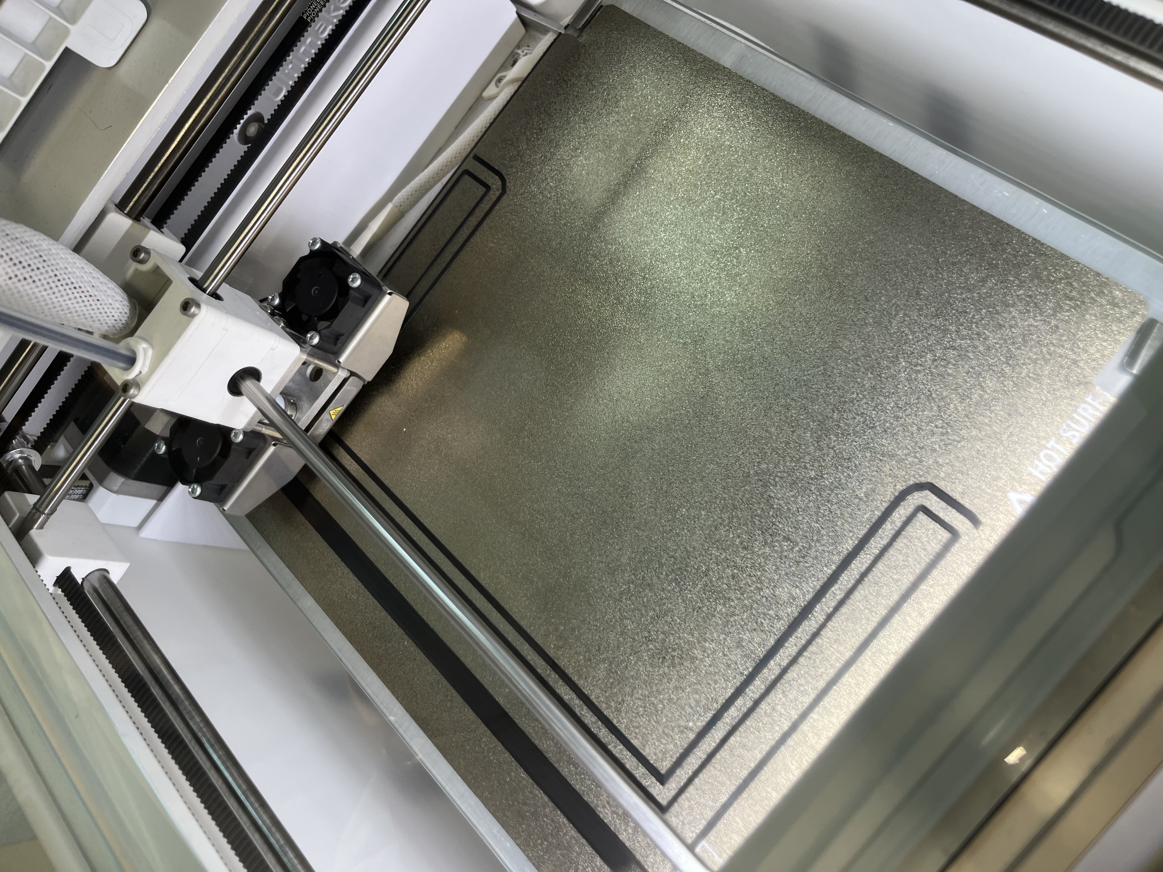
When the design was finished we exported the file in a .stl file. With the .stl file created we can now open the file in Cura Ultimaker to start with the printing. To print out the letter we use the printer Ultimaker 2+ connect with the following settings allowing us a design that is thin enough to let the LED-light through but also maintaining a nice design.
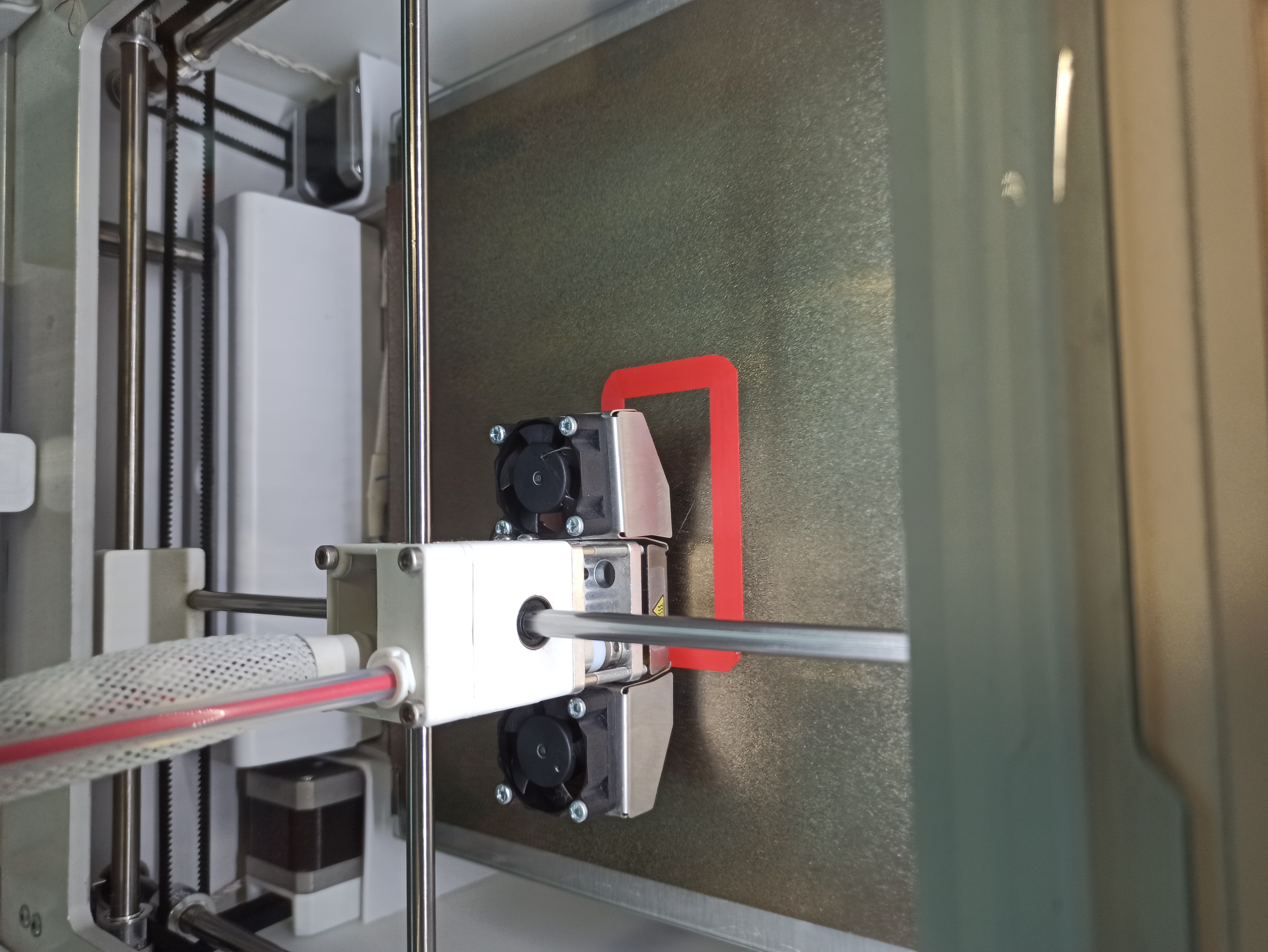
The process of printing took 1 hour and 50 minutes with a total weight of 22 grams. The steps of the process are documented with the following images:
The process at the beginning looked like the following: 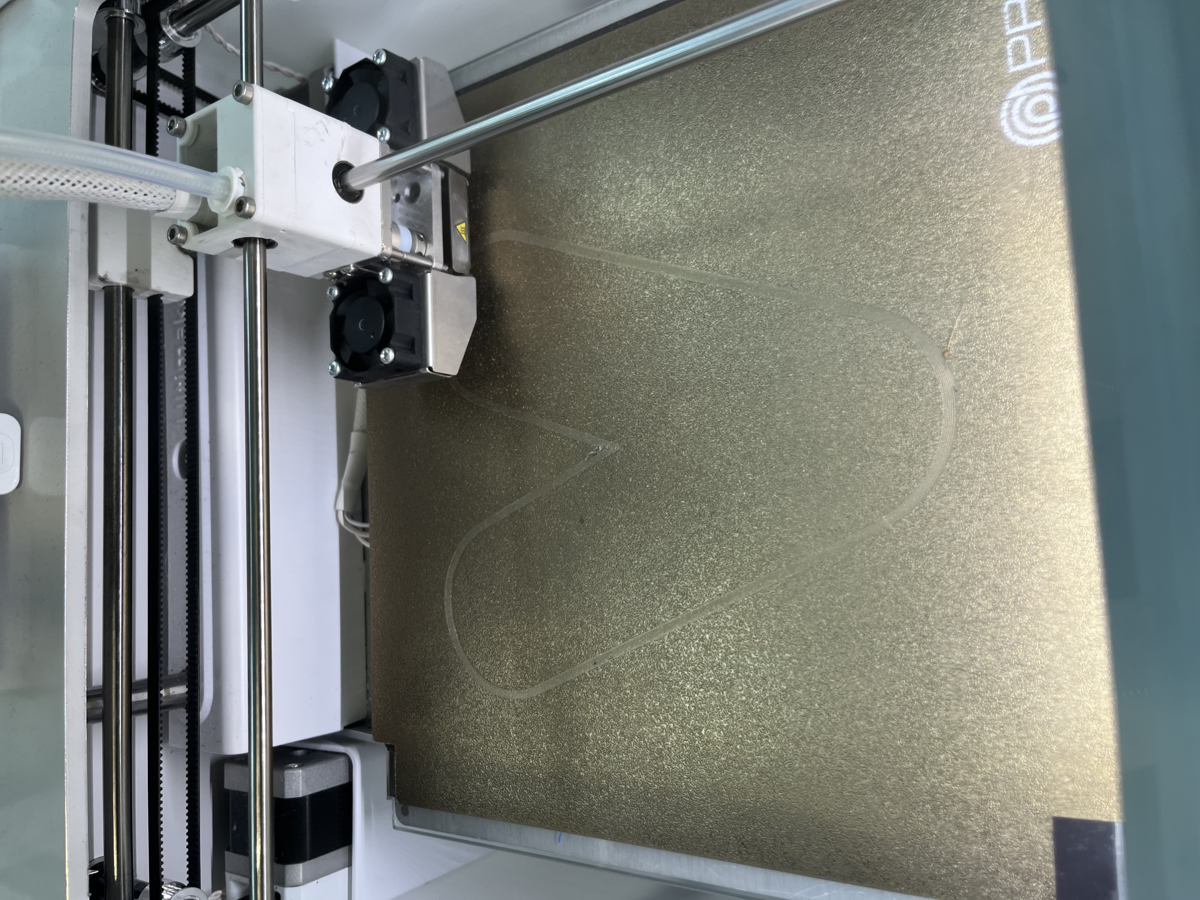
The process of printing in the middle fase looked like the following: 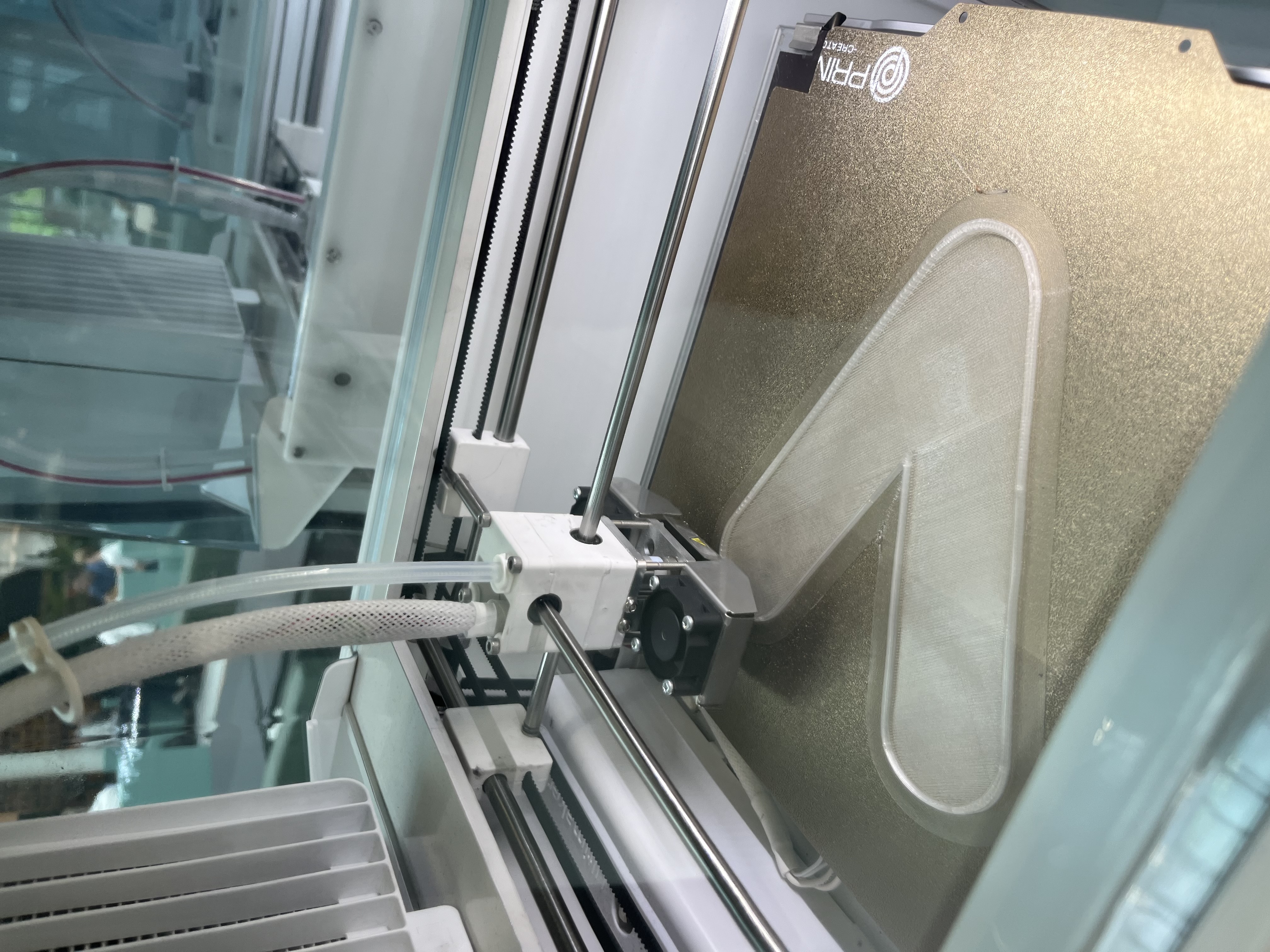
The end print looked like the following: 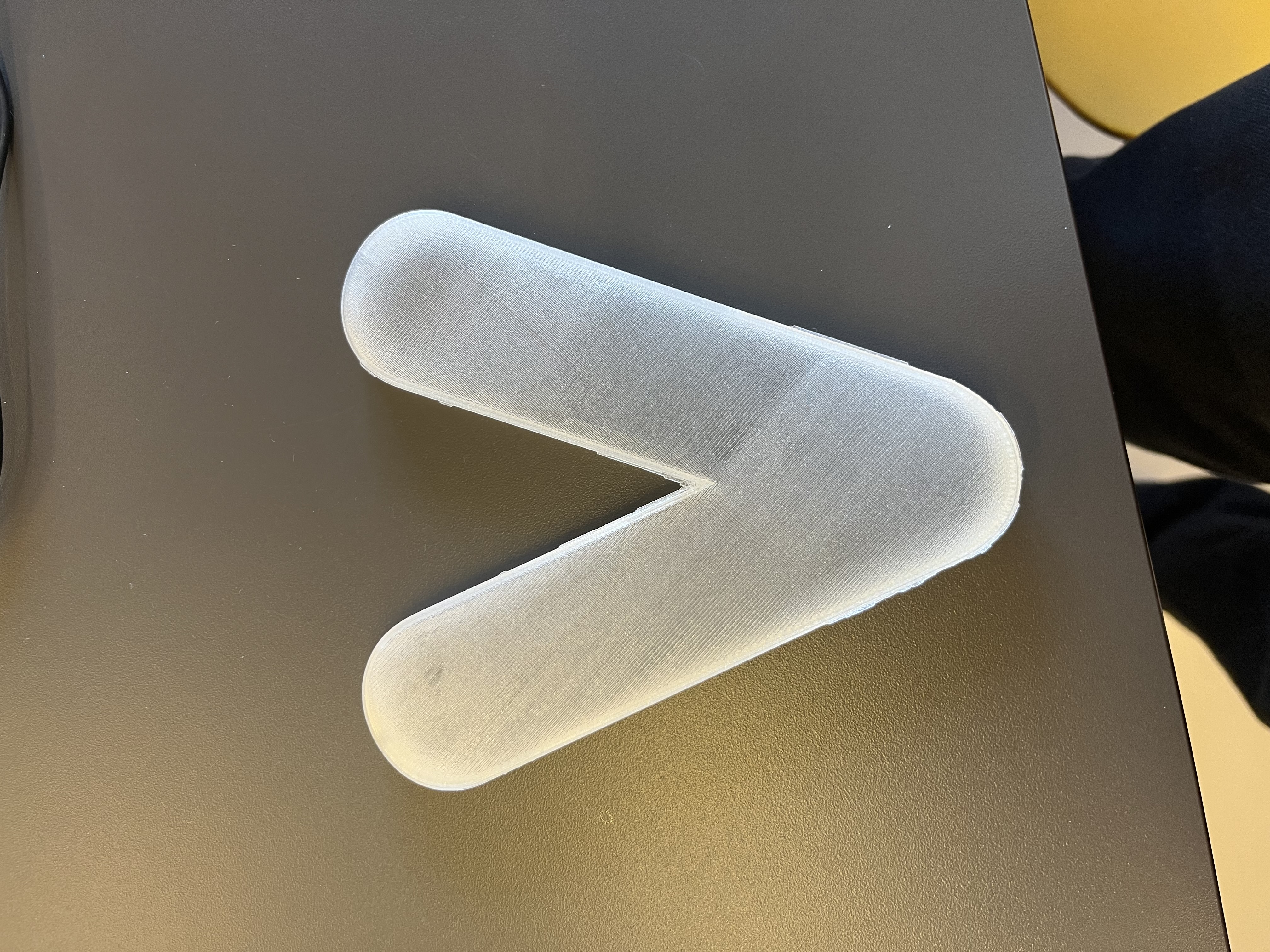
The end-product came out how we wanted. We now need to test the design with thw working led-lights in it to see if the sizing is correct. Also the letter might be to big for the board that we want to make, so we need to do further testing to see if we need to re-adjust the size of the letetr in the end.
Box
To make the box we used the design mentioned in the concept & design. Because we want to use this for the laser cutter, we have to export this design to 2D images, for each side. Luckily there is an option in Fusion to export different sketches (sides) to .dxf files, which are 2D designs.
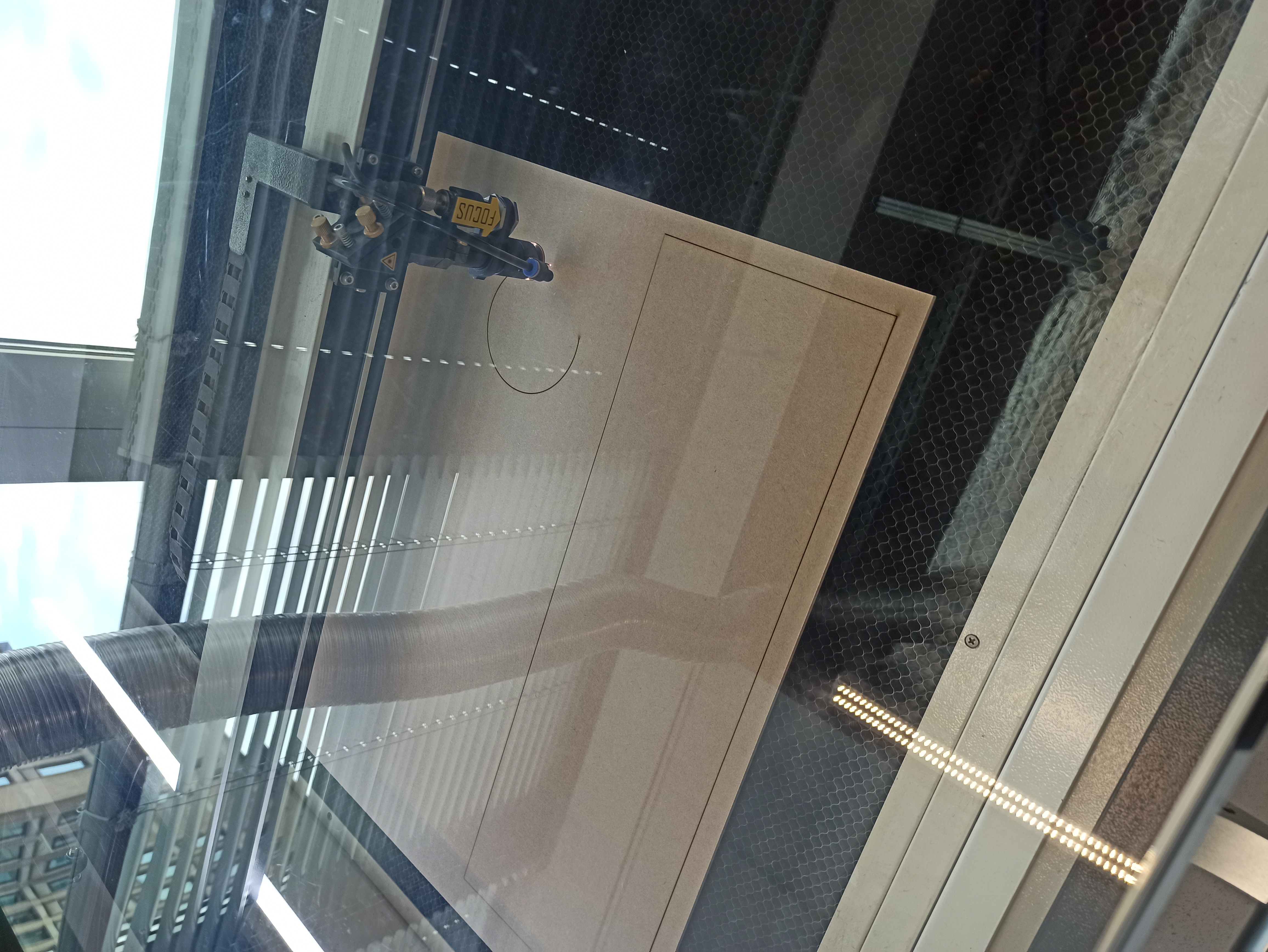
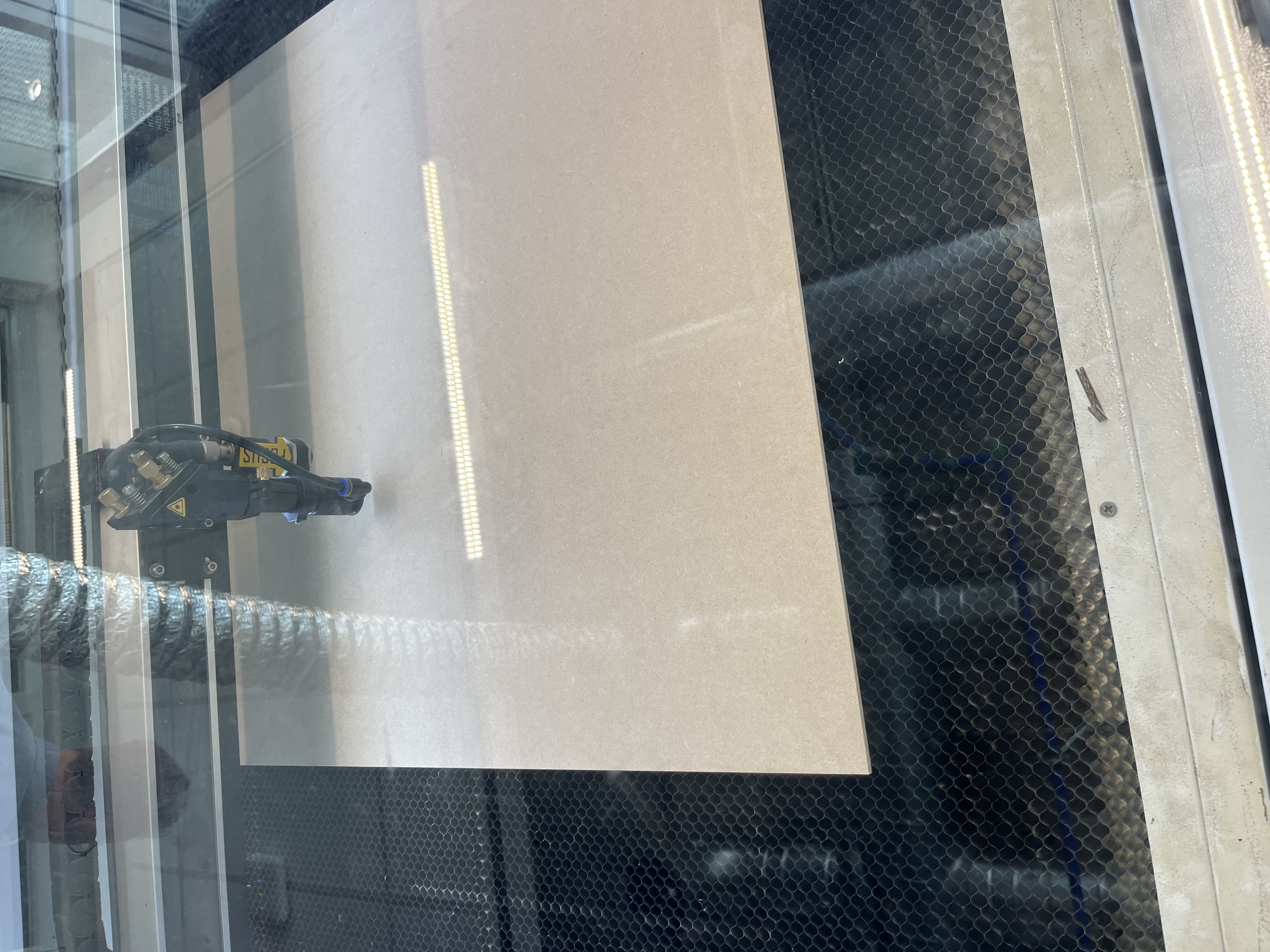
The wood we bought was a 60x60cm plate of MDF of 4mm thickness. Since they already had preset settings for this on the laser cutter, we simply used those:
The process went quite fast, here is a picture during the cutting process.
When all was done we were left with the following pieces. As you can see it does have some scorch marks on the bottom of the panels, but the top looks good, therefore there was no need to redo it. Perhaps in the future, a lower power can be used.

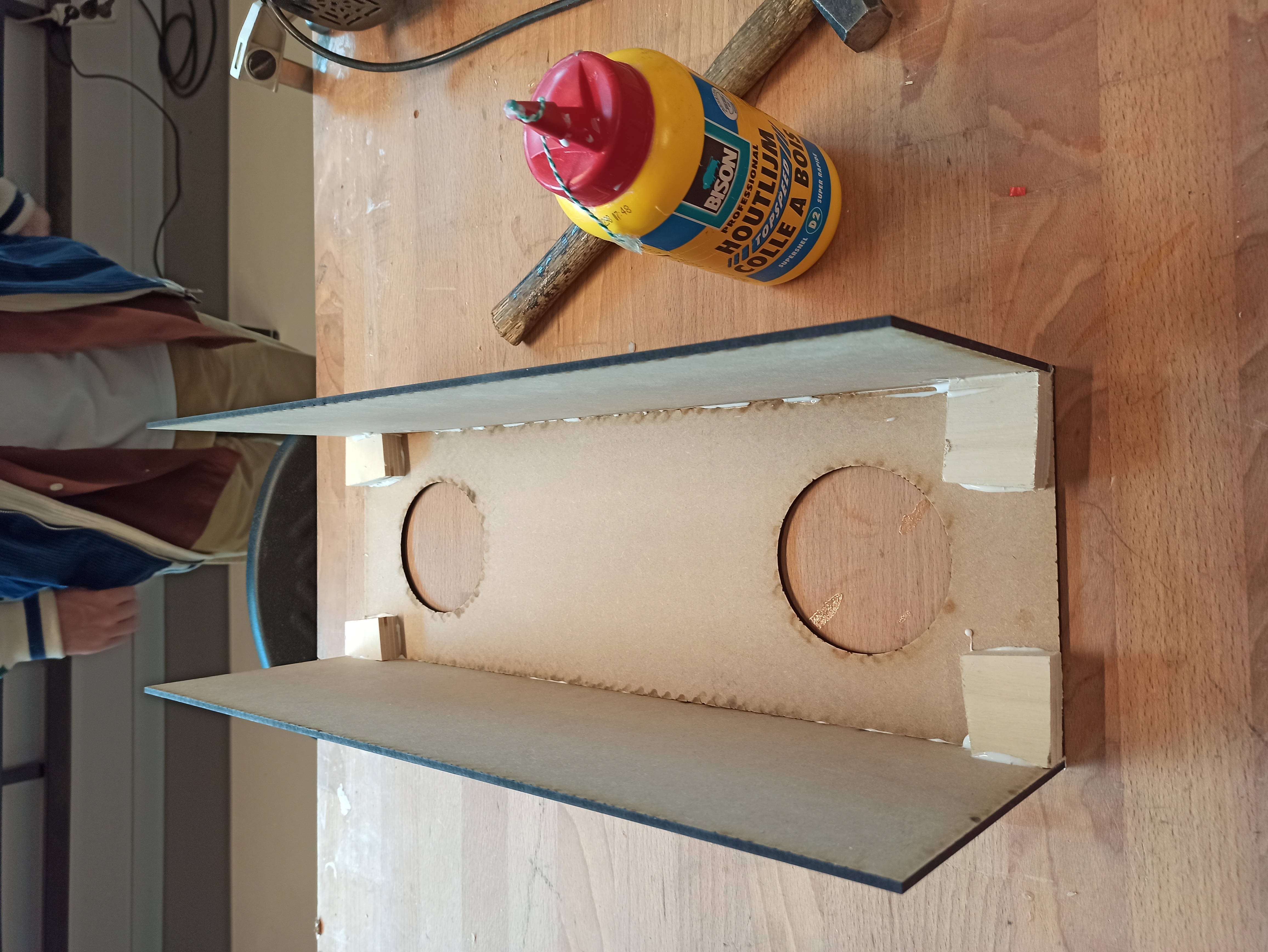
All that was left now was to assemble the box, since we wanted a clean exterior, we have used glue to assemble the box. However we did need some block to make the surface area of the glue larger, to make a stronger construction. For this we used some scrap wood. It might not looks so good, but since this is the inside of the box, it does not matter.
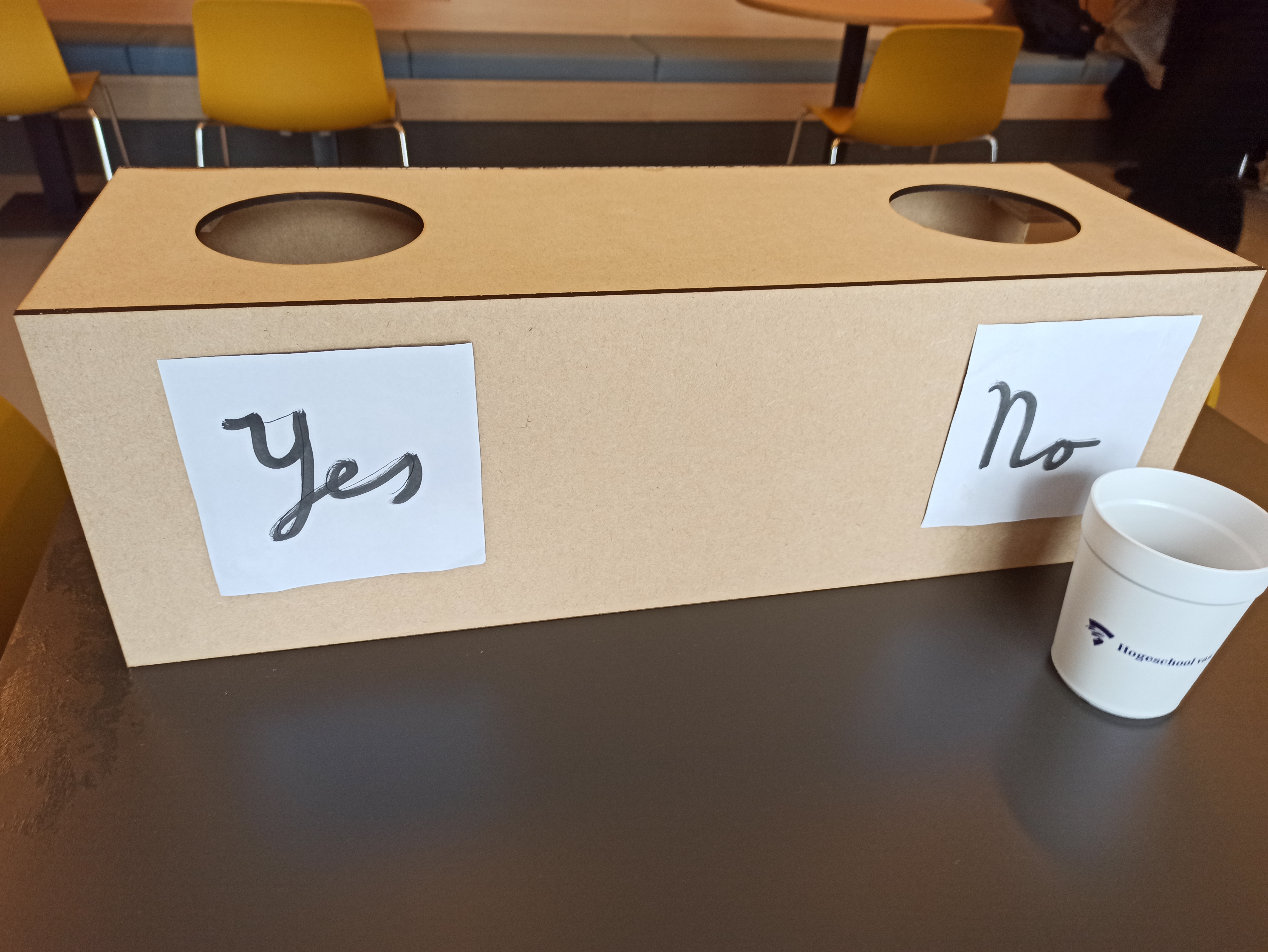
When this dried we are left with the final product, which can be seen below.(the yes/no signs are not part of the box, purely for display).
Board
The board needed to draw the users attention was eventually cut from a piece of MDF wood. To realize this a simple svg was created.
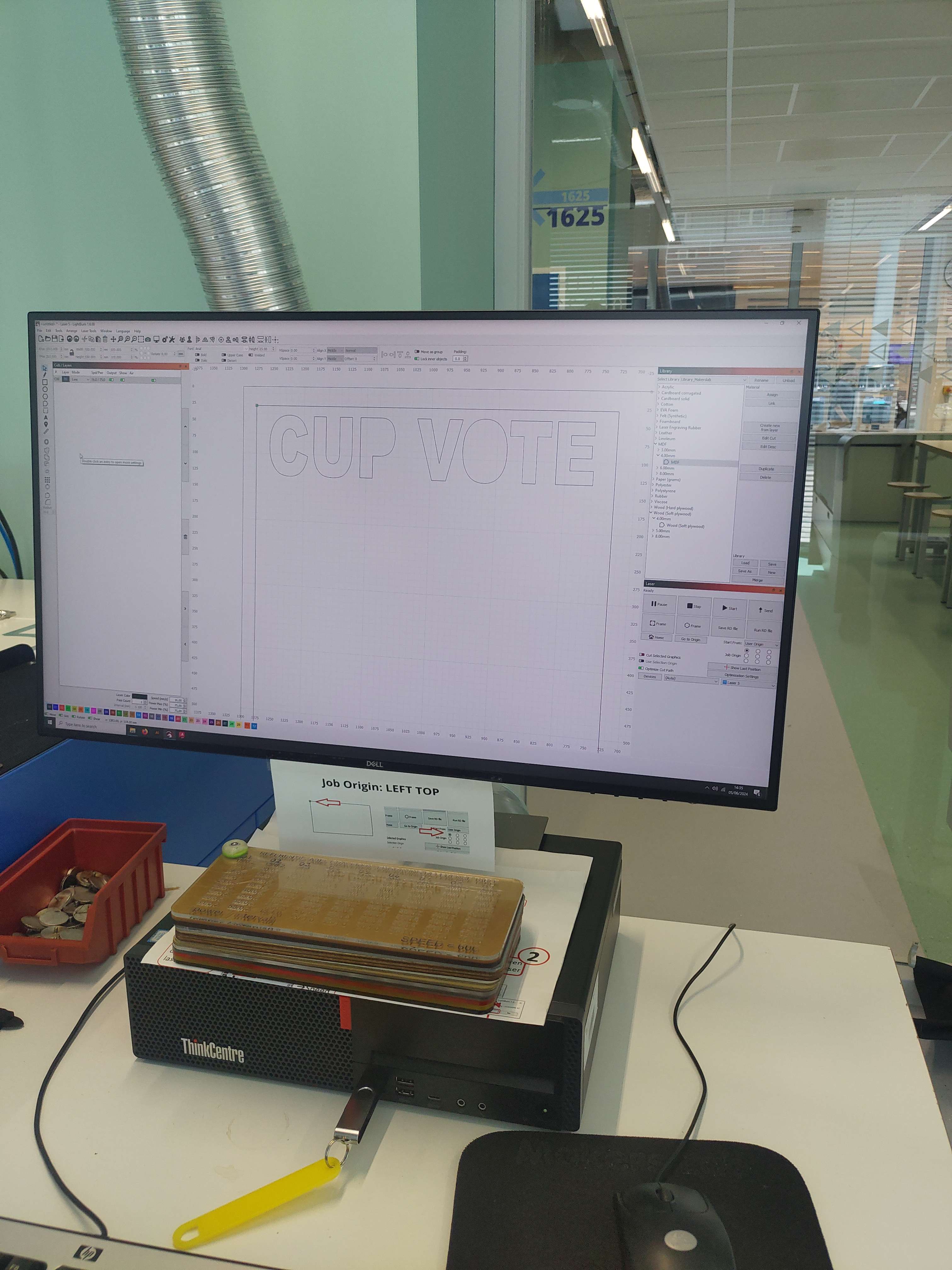
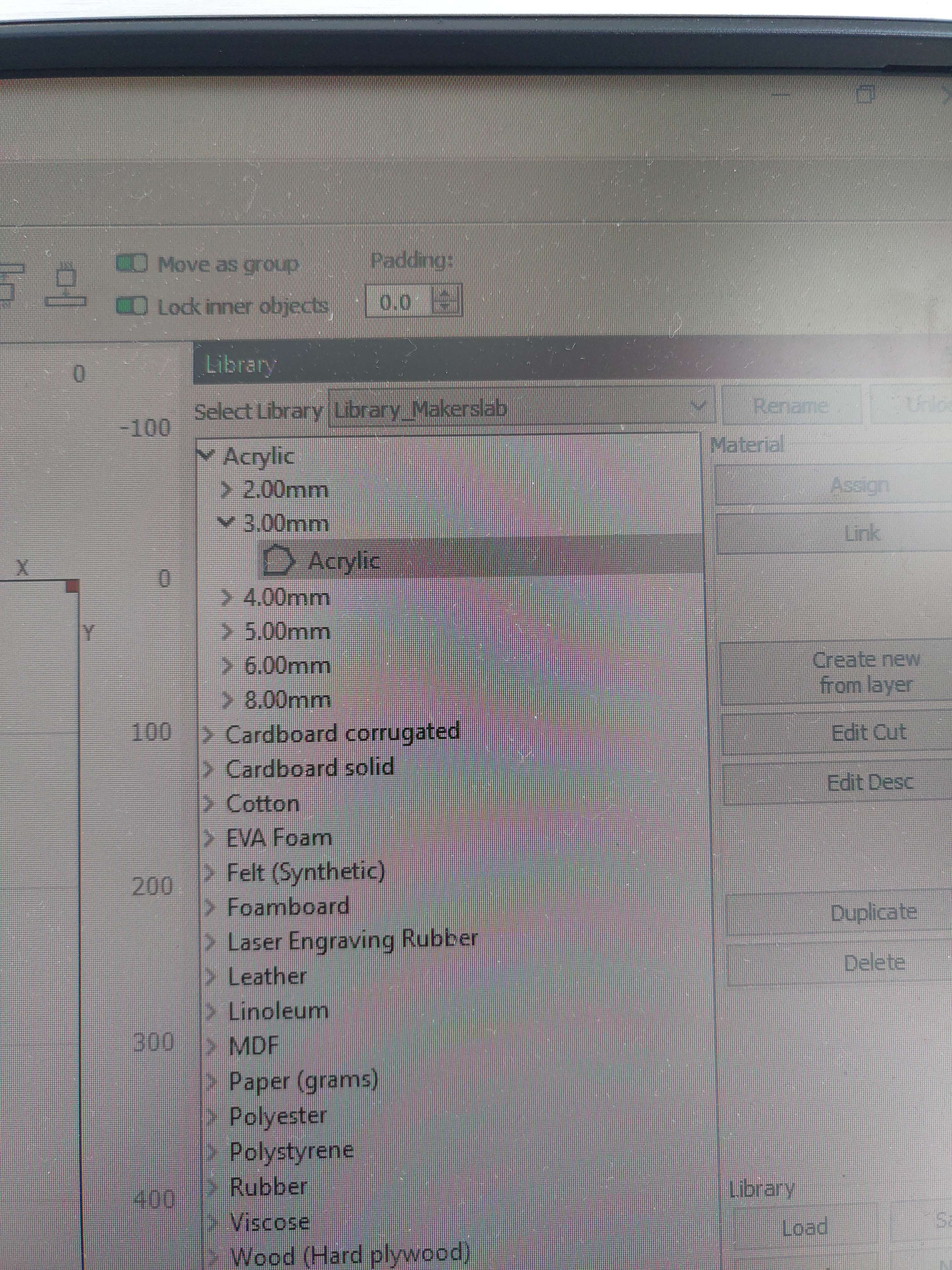
Here the svg was loaded into the software used to control the laser cut machine. Within this software you can add small changes to the file if needed.
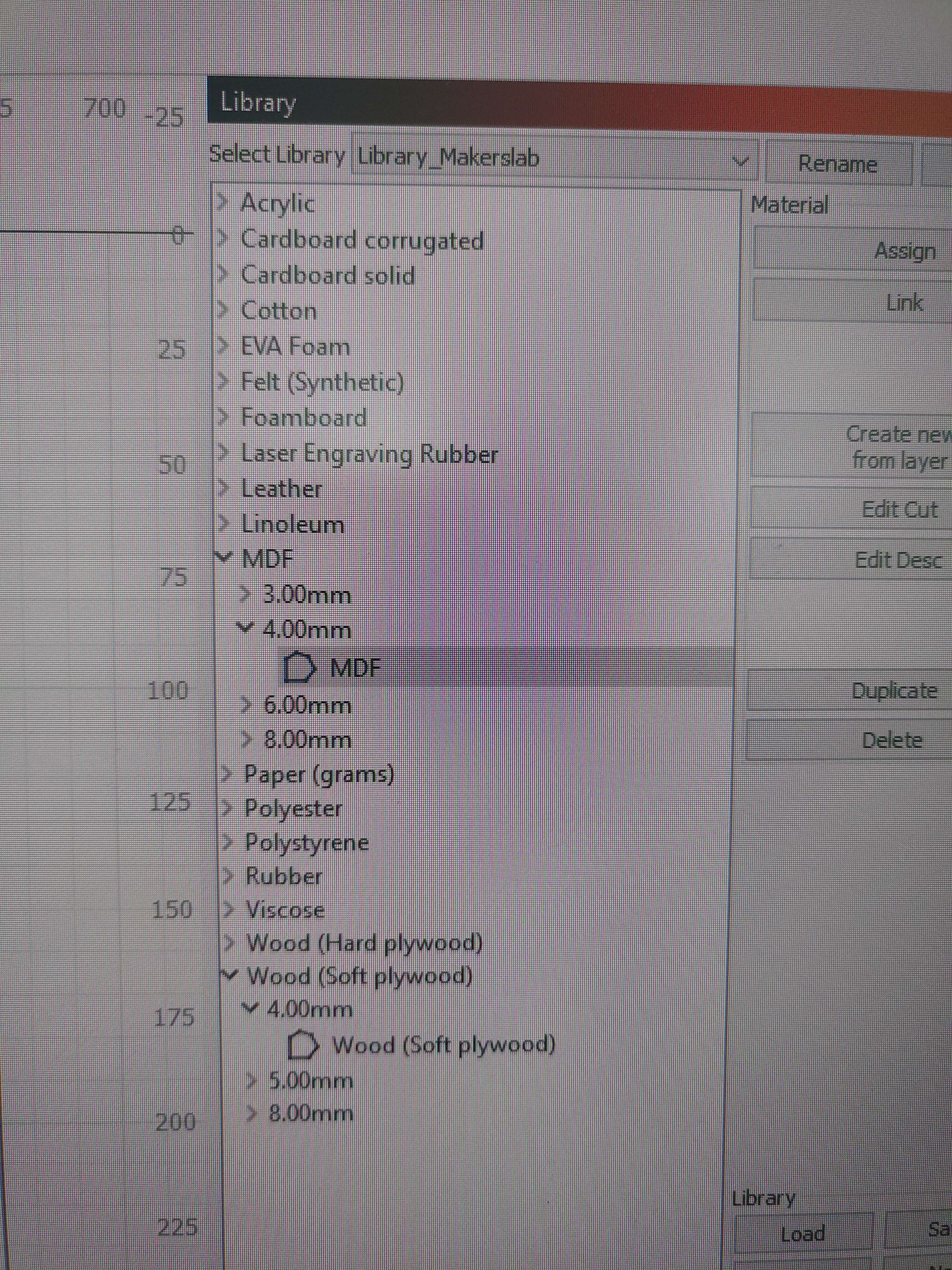
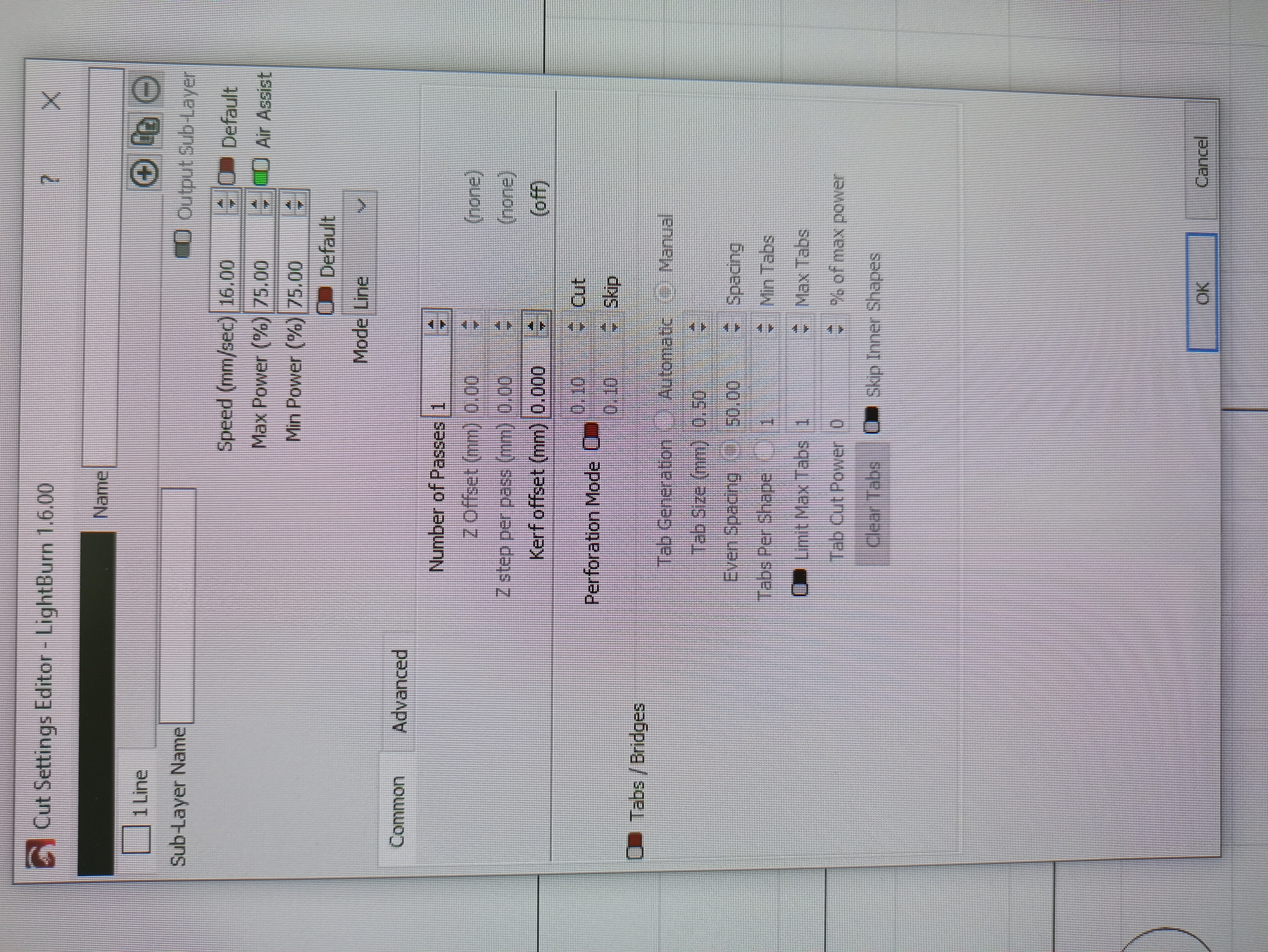
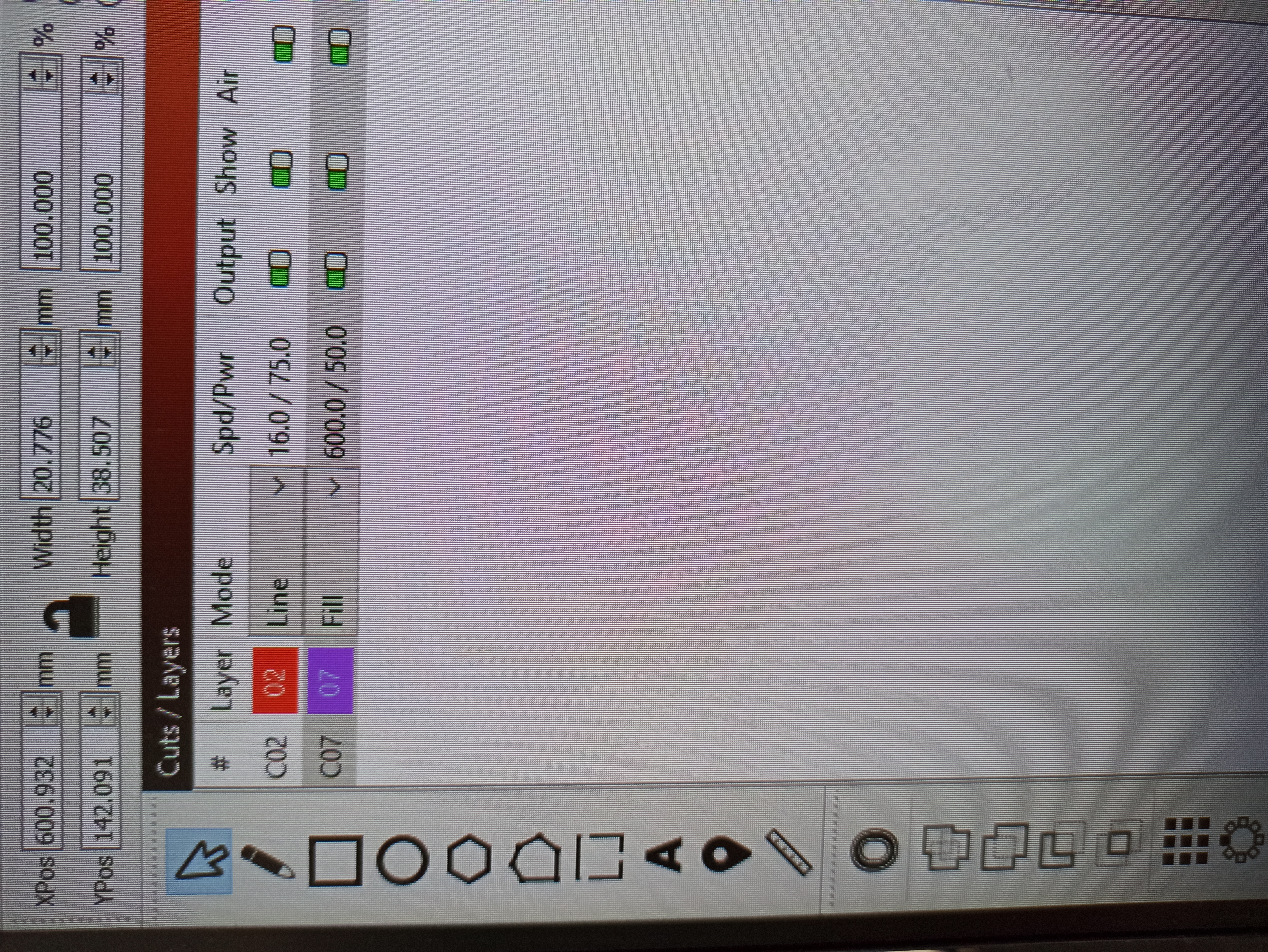
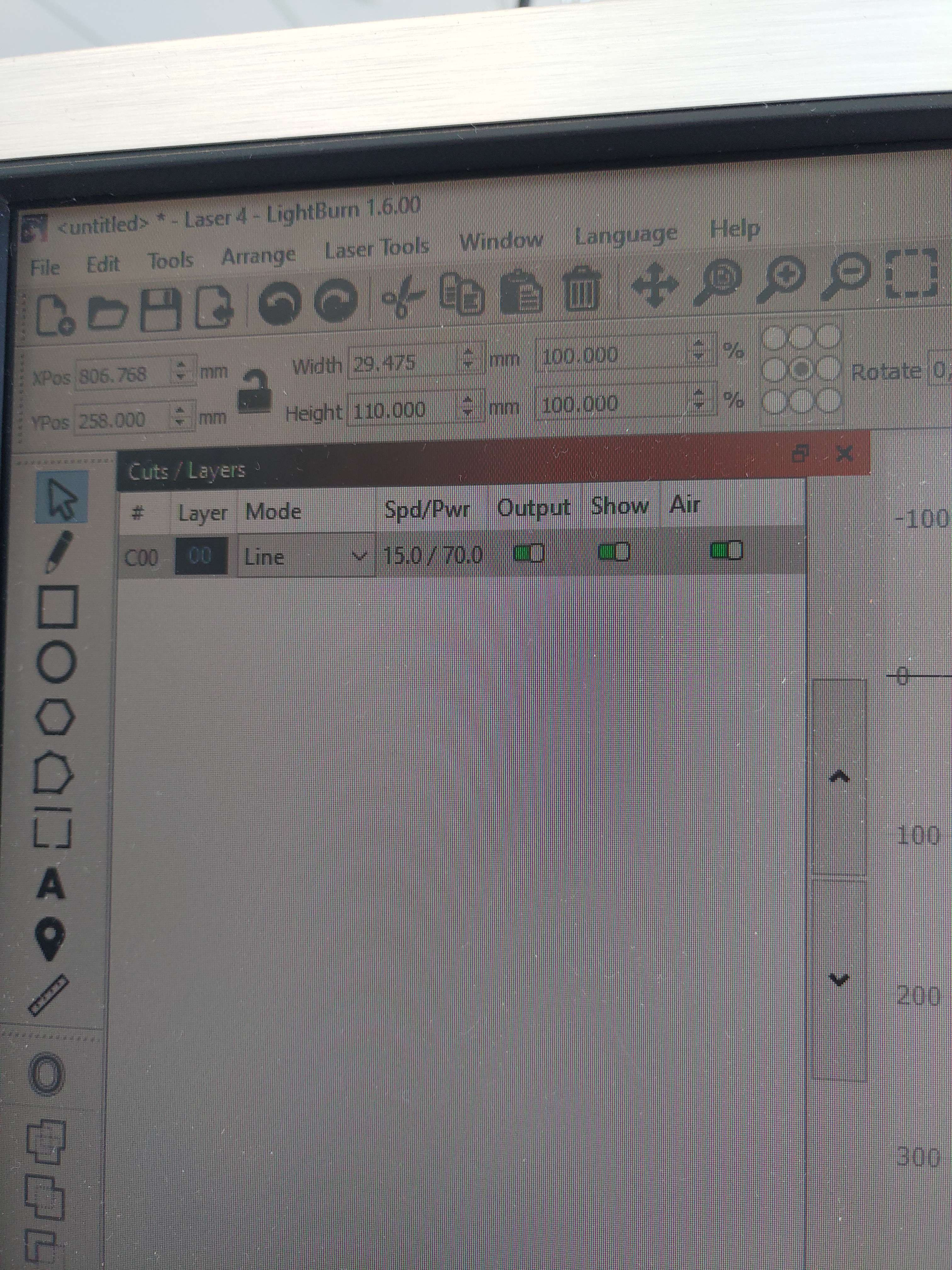
Within the software one needs to select the material that was being used. The tickness of the material should also be provided.
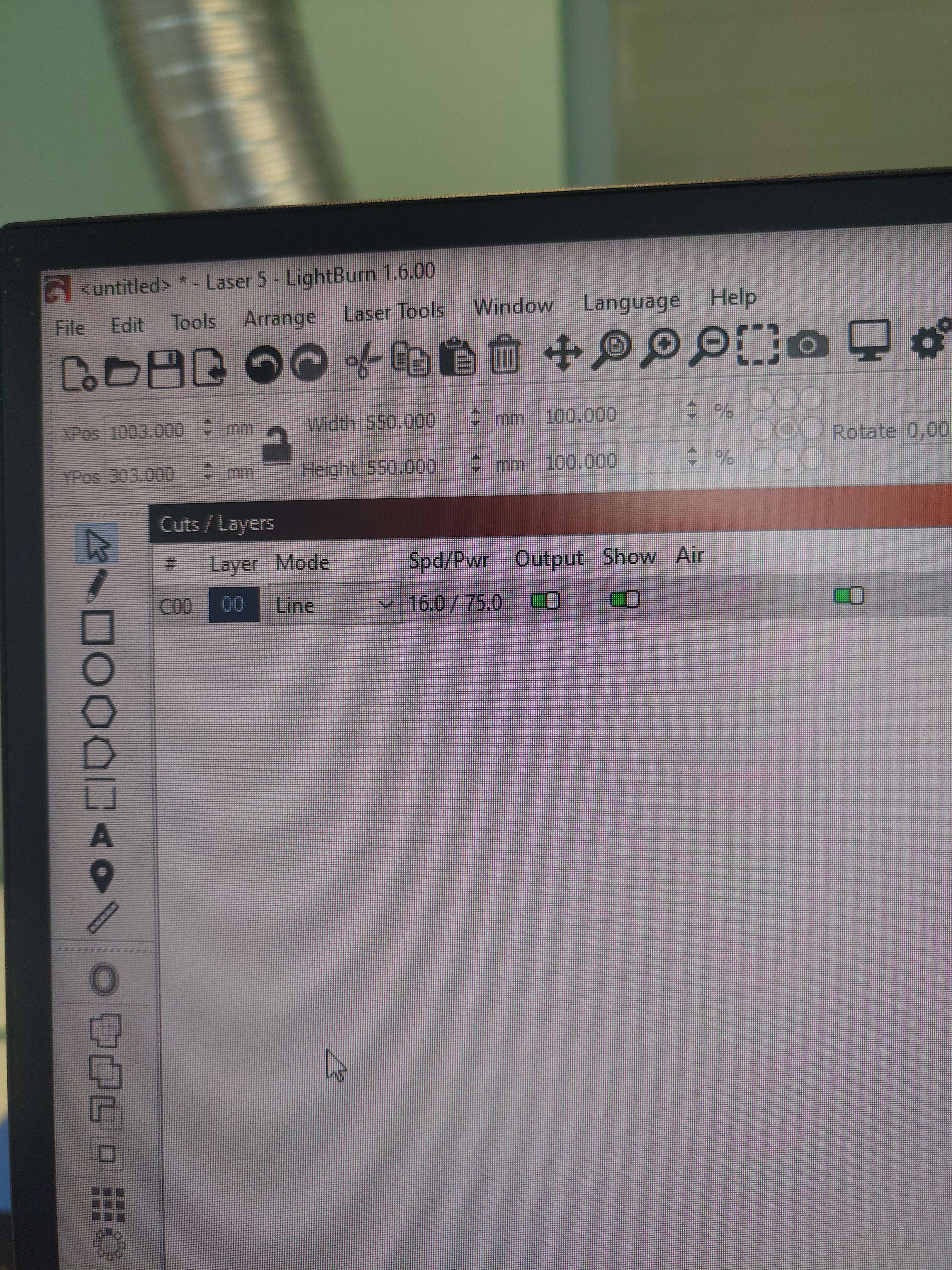
Then the power settings and the settings for the speed of the movement of the laser is automatically filled in. These settings will need to be send to the laser machine itself. The software has a single button for this.
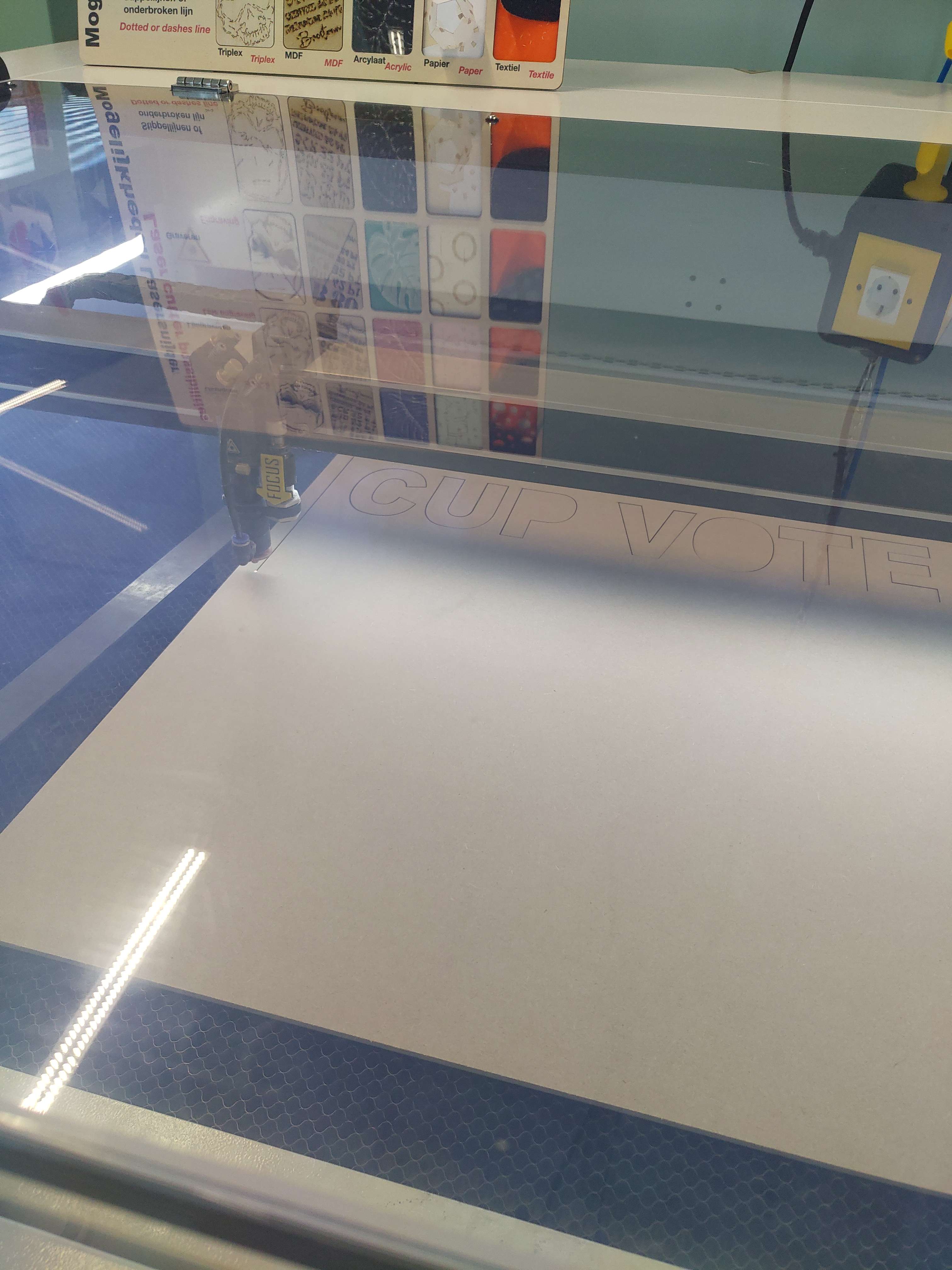
On the laser cutter itself the focus distance should also be calculated, luckily the machine can do this on its own. One should feed the material into the machine after which one should position the laser above the material. Then one can press the "focus" button and press enter. The machine will automatically set the distance between the laser and the material.
Then the machine can simple be started by pressing the start button.
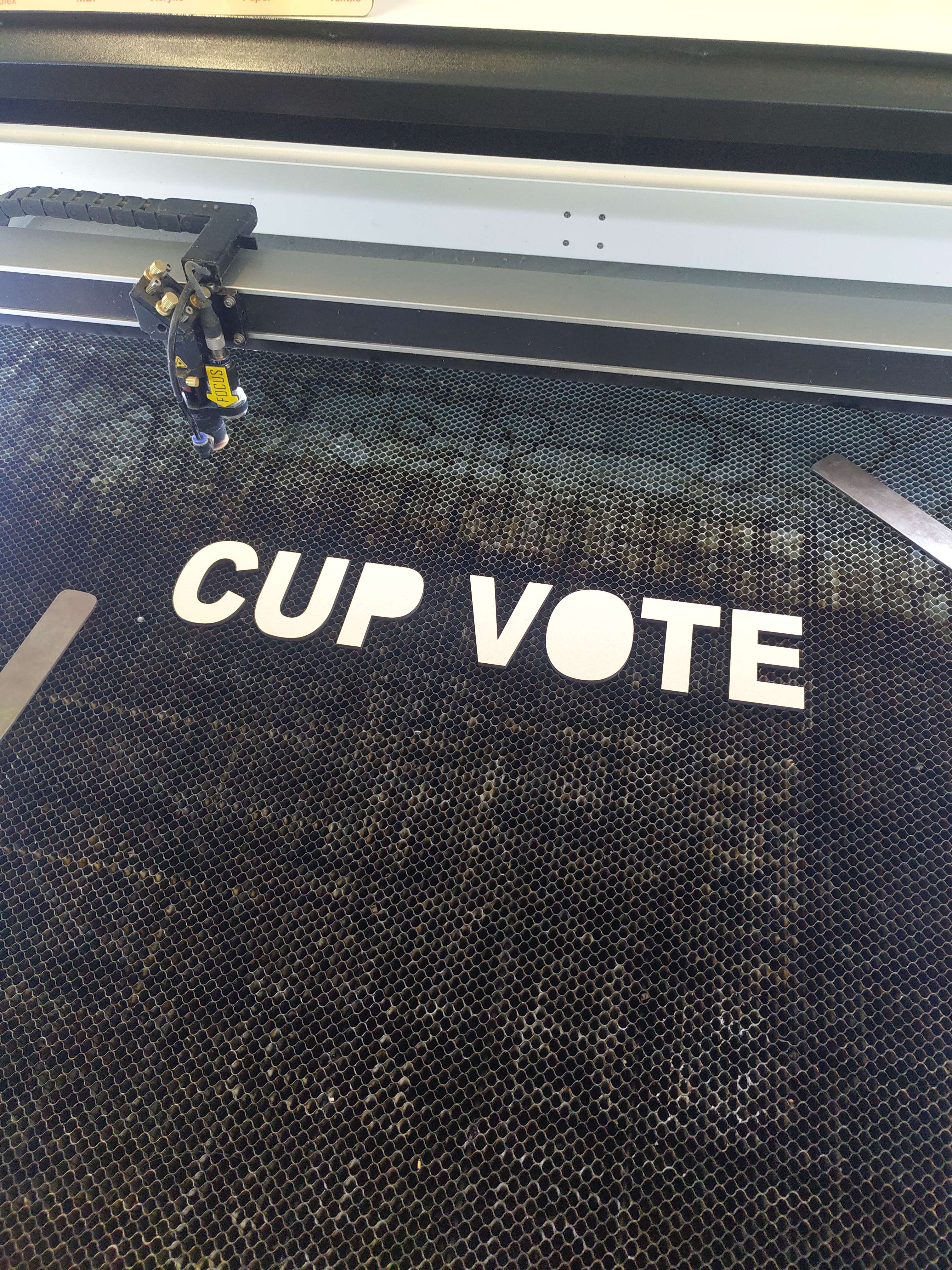
In the end the cut material can be lifted from the cutting bed which will reveal the excess that's left of the material. These extra pieces can be thrown away or be used in other projects.
YES/NO meter
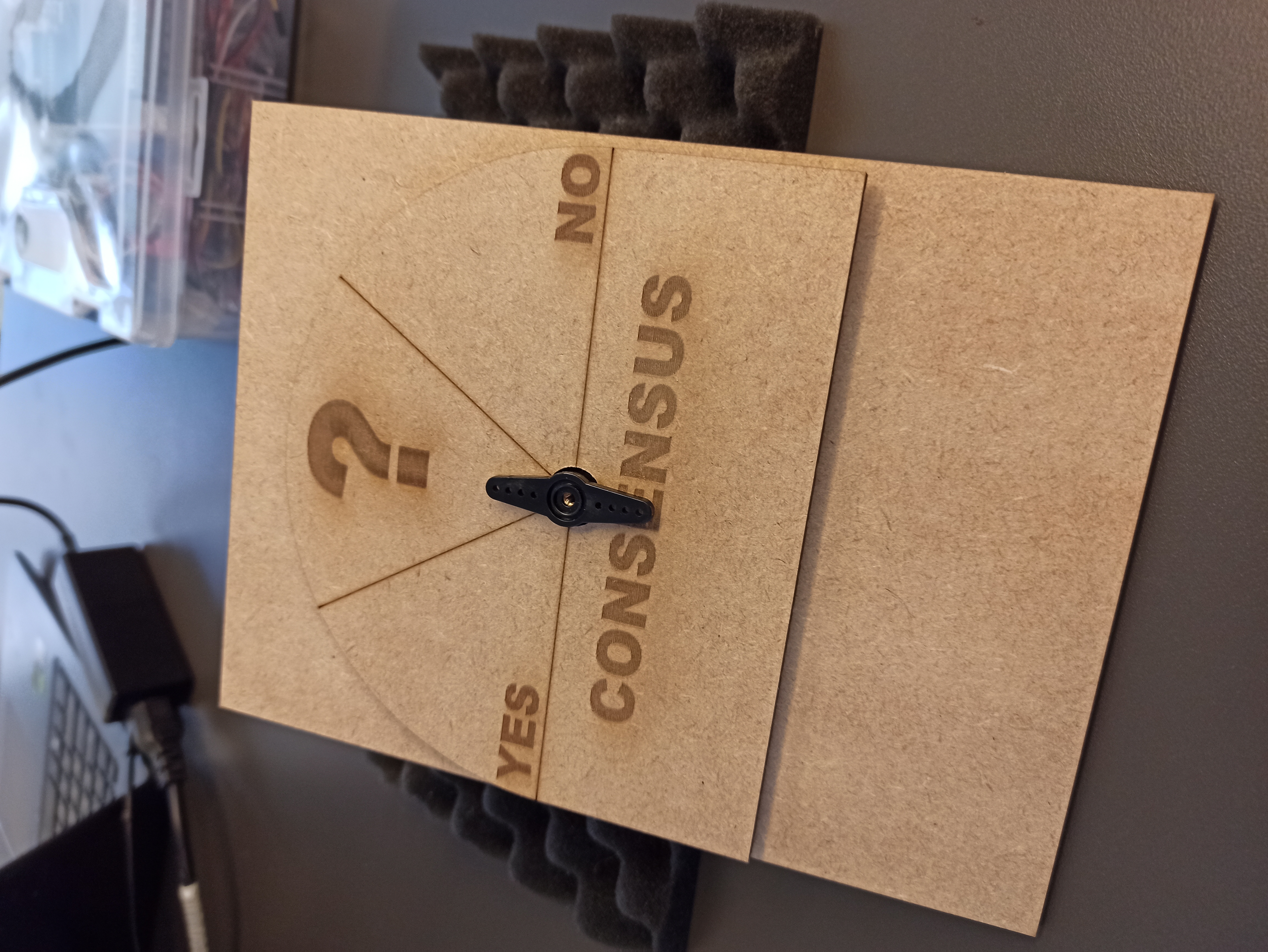
One feature of the concept is adding a meter which tracks how users have responded to a question. Think of a half-circle with YES on one side, and NO on the other. An arrow will then roughly indicate how the other users have responded.
The first simple concept is seen below: 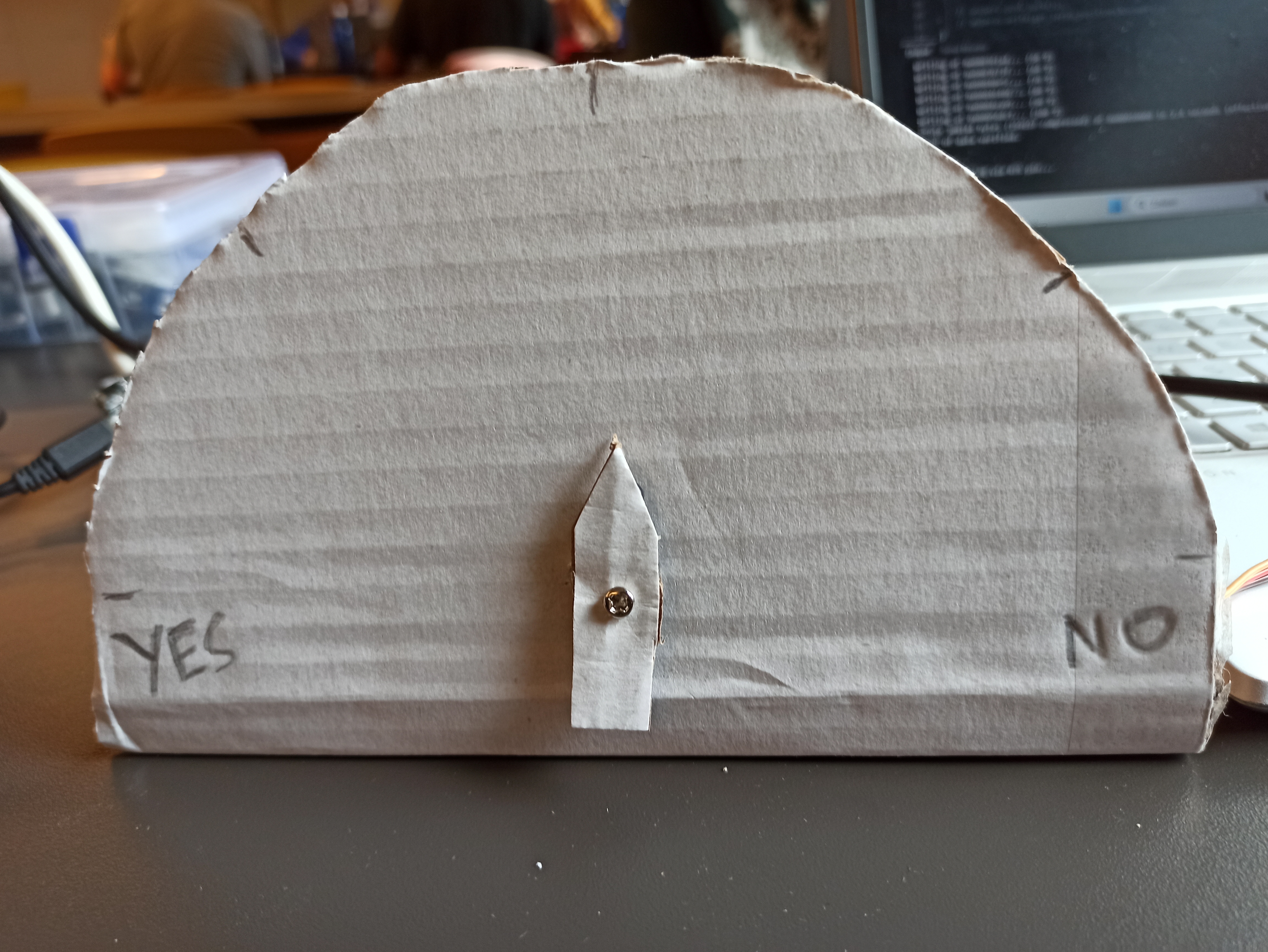
Prototype assembly
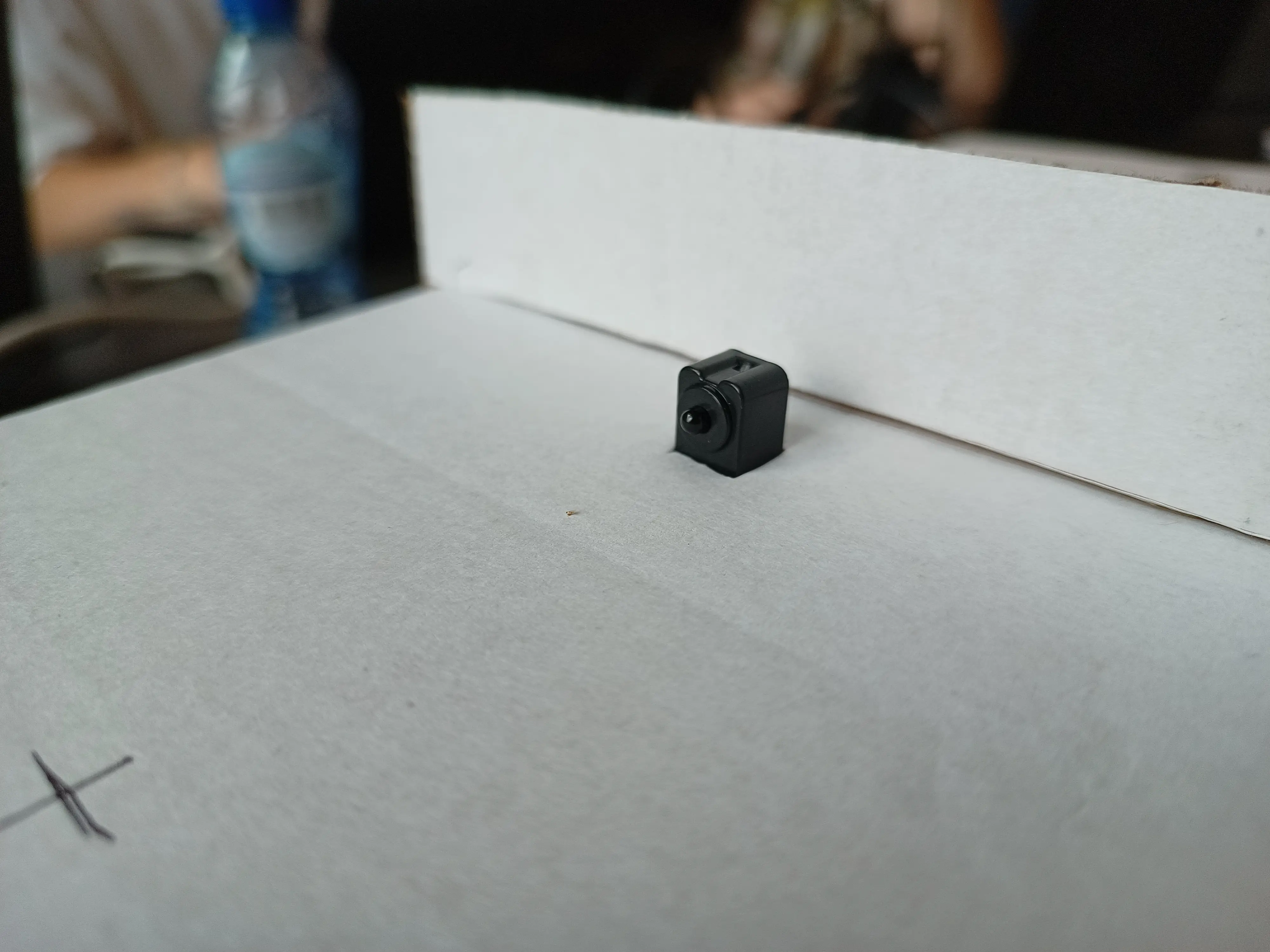
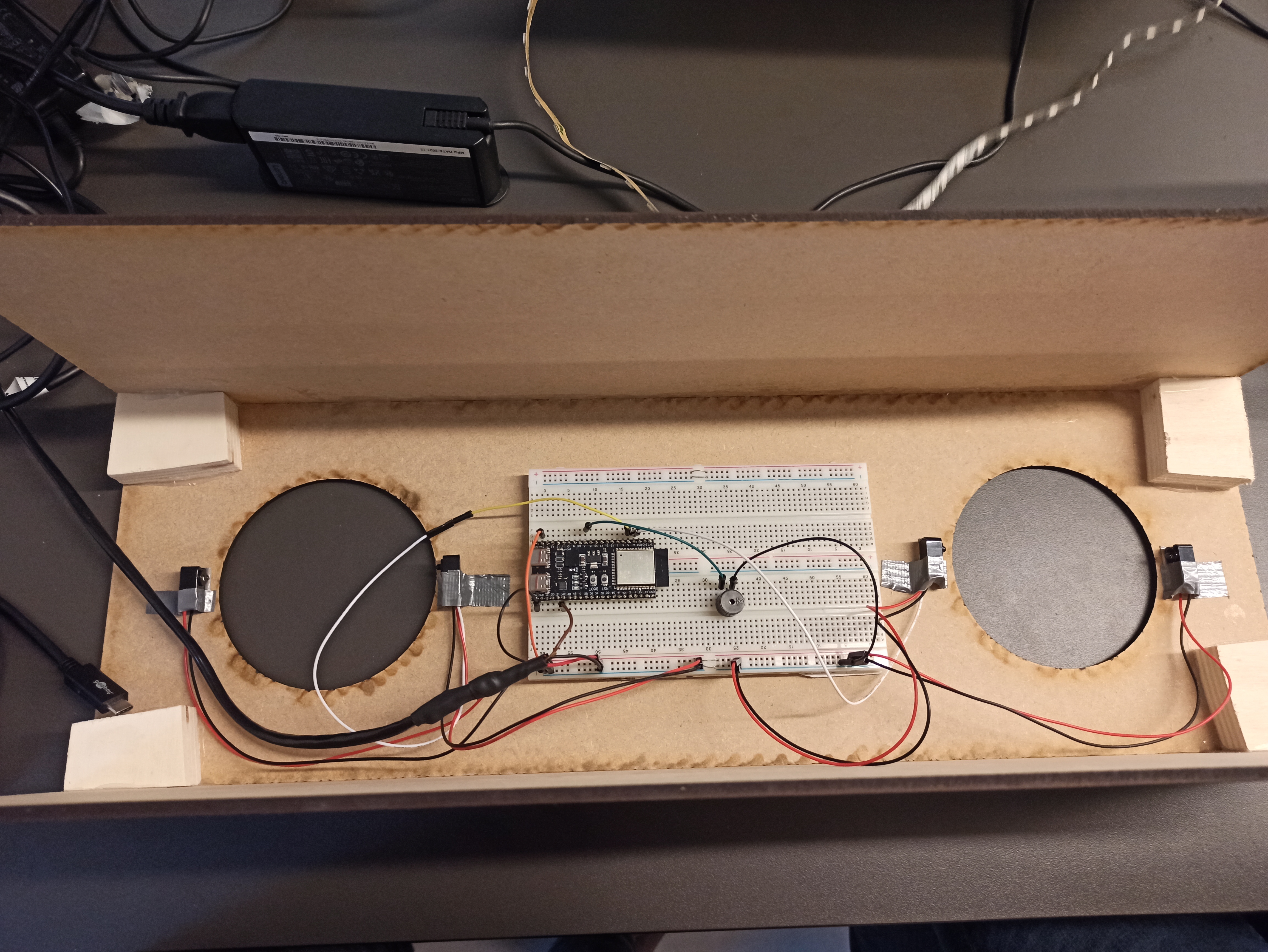
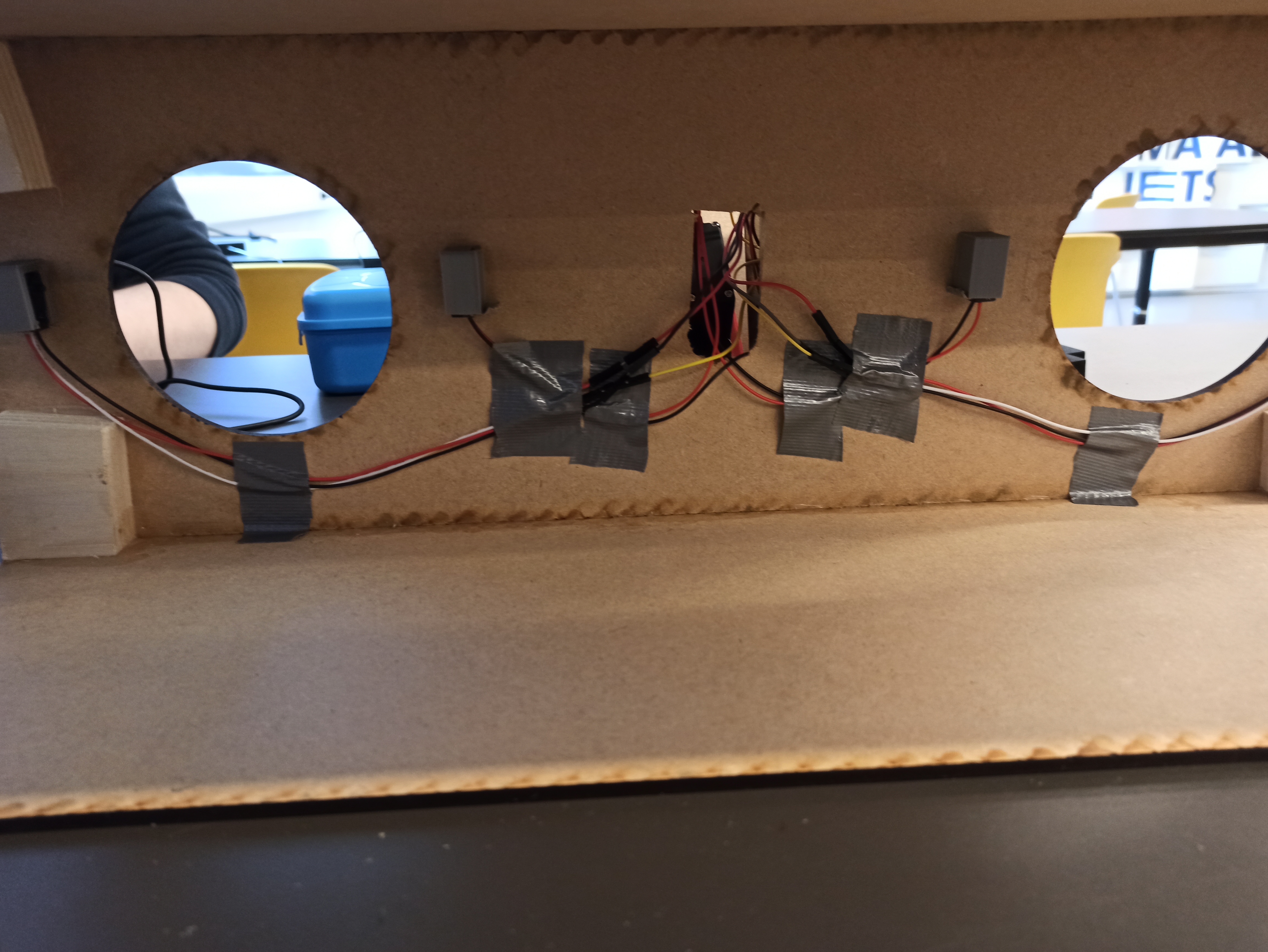
During this sprint we have made multiple separate parts, therefore these still have to be assembled. This also includes mounting the sensors on the device.
For this sprint we simply used tape to attach the sensors to the housing, which can be seen below. The embedded device is also attach to the top of the housing, this will probably change for the next iteration.
 .
.
The LED strip is mounted behind the sign for this iteration. This way is shines through the letters. All in all the Sprint 2 prototype looks like this:
When answering, the device will make a sound and the color of the LED will change. This can be seen below:
Testing
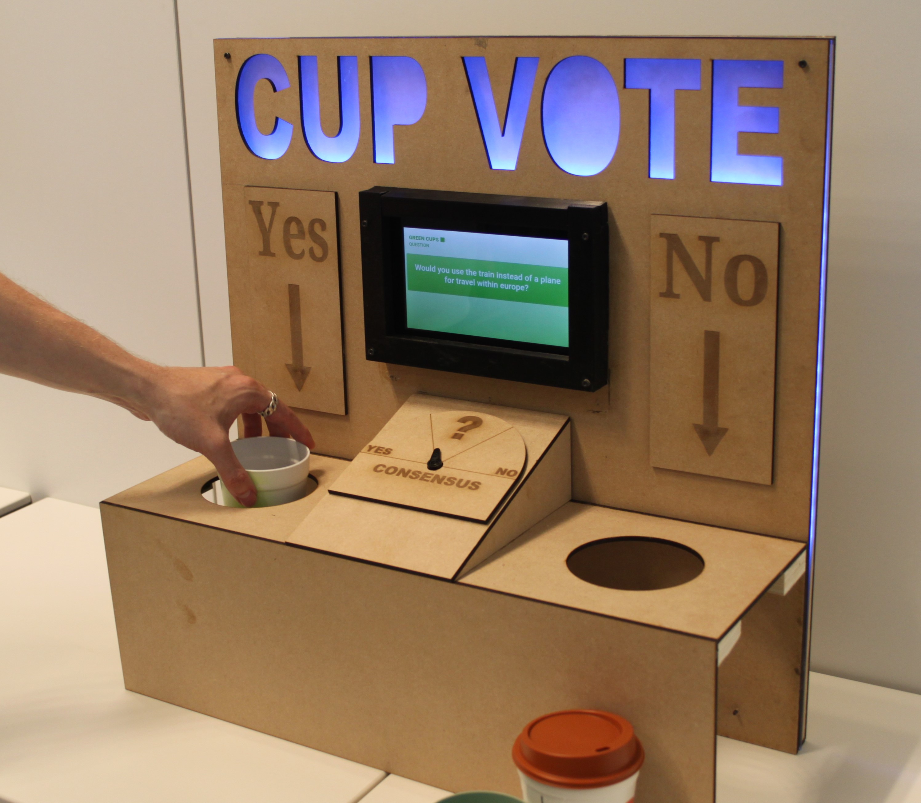
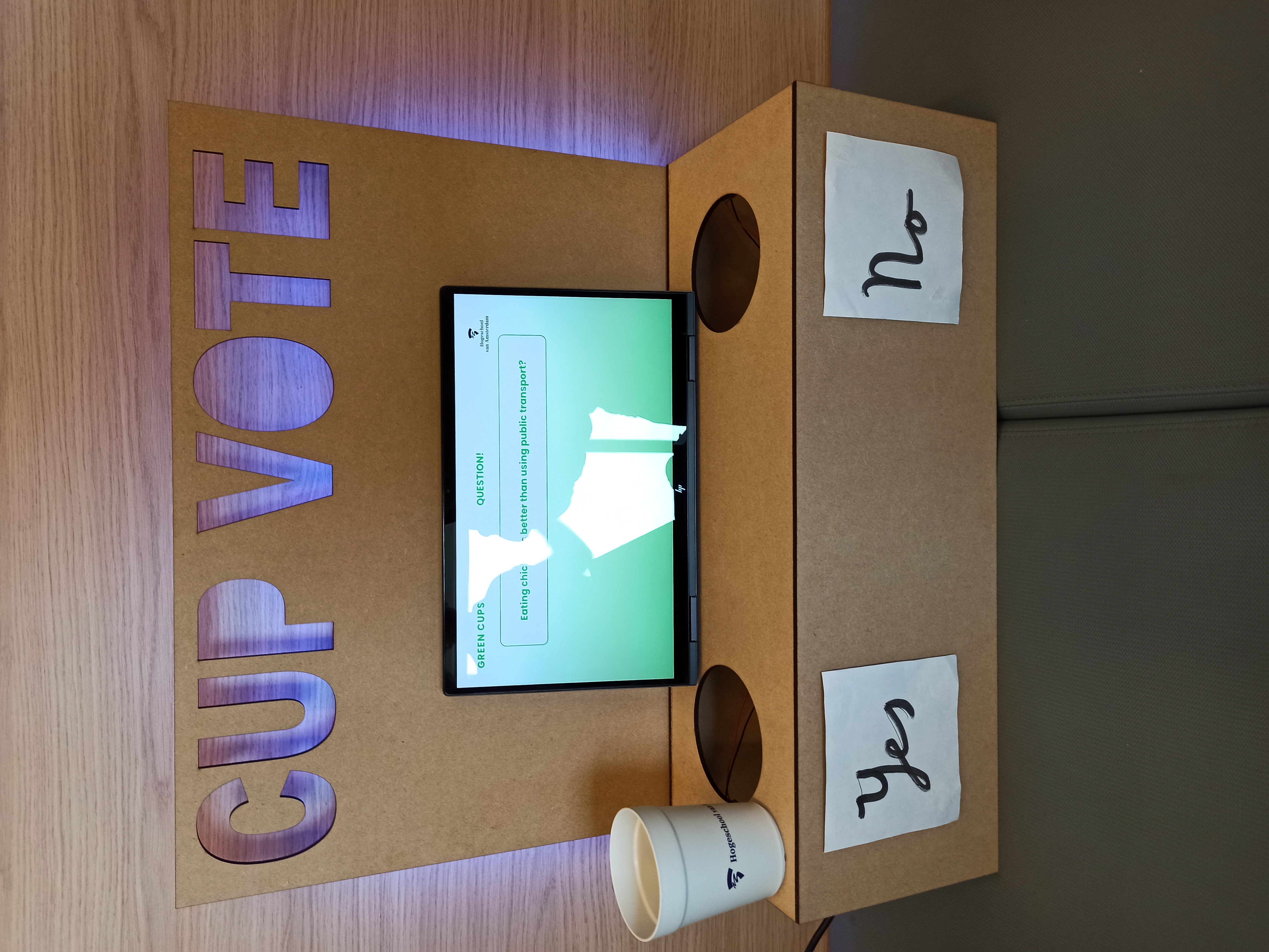
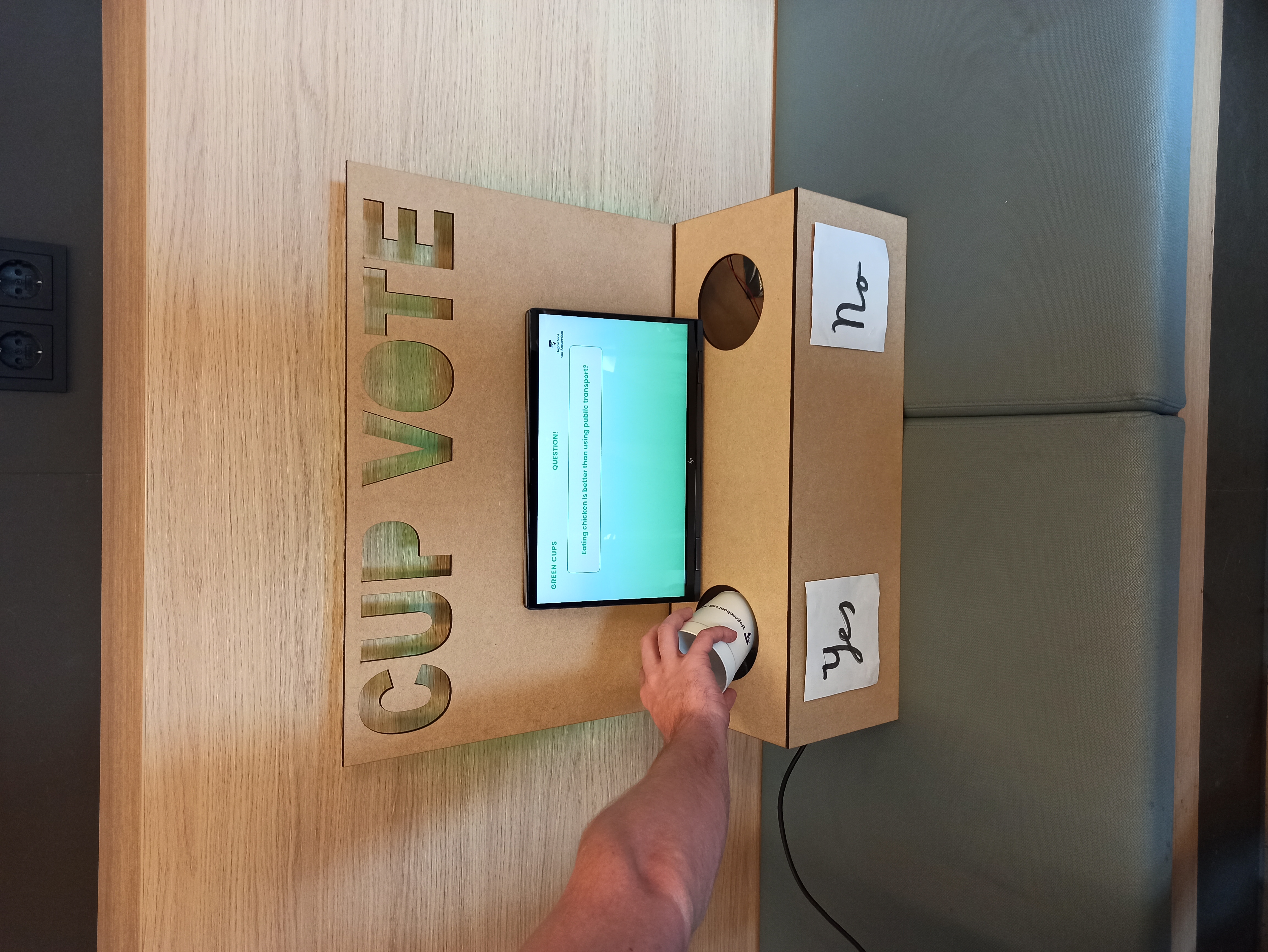
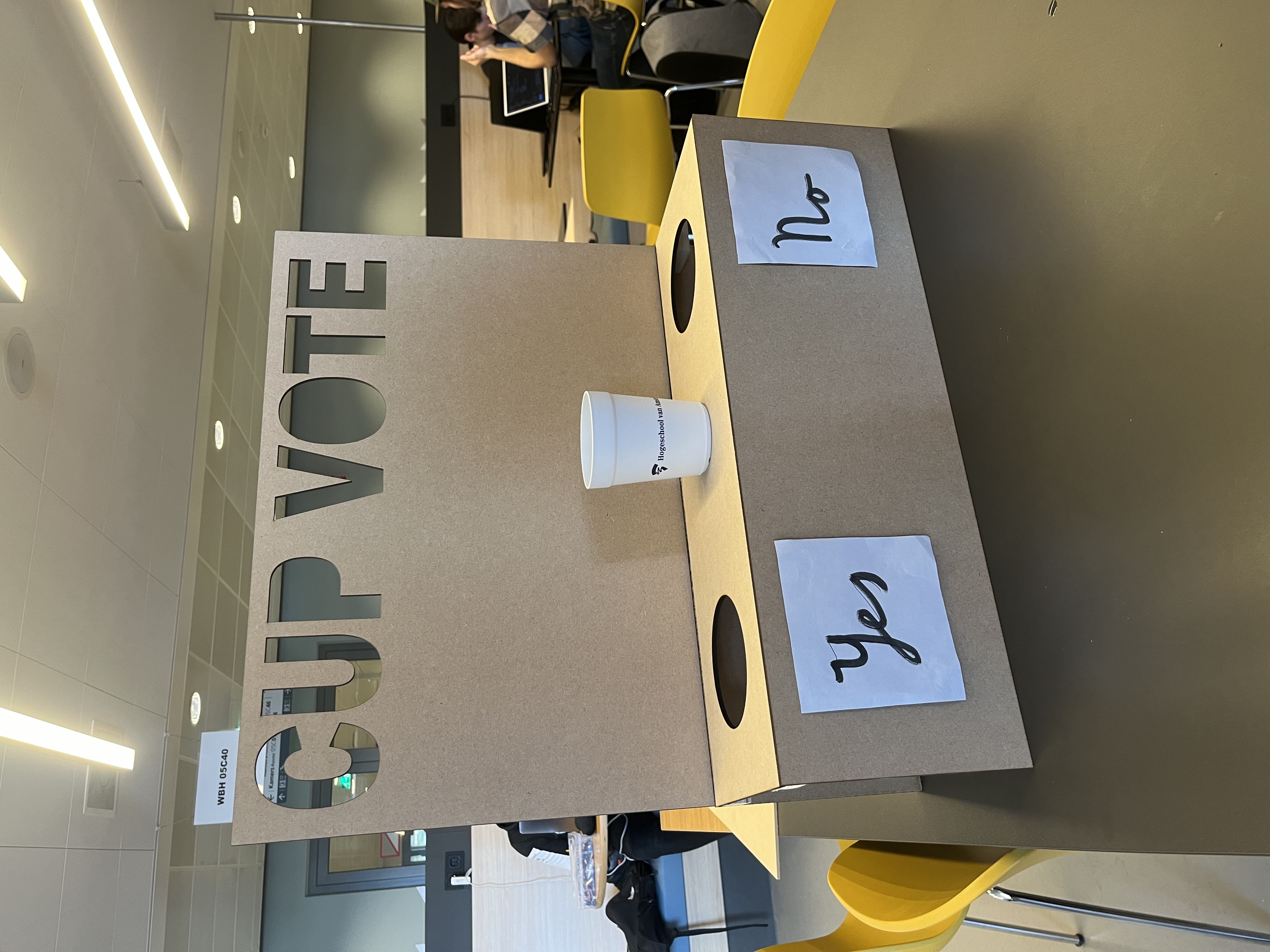
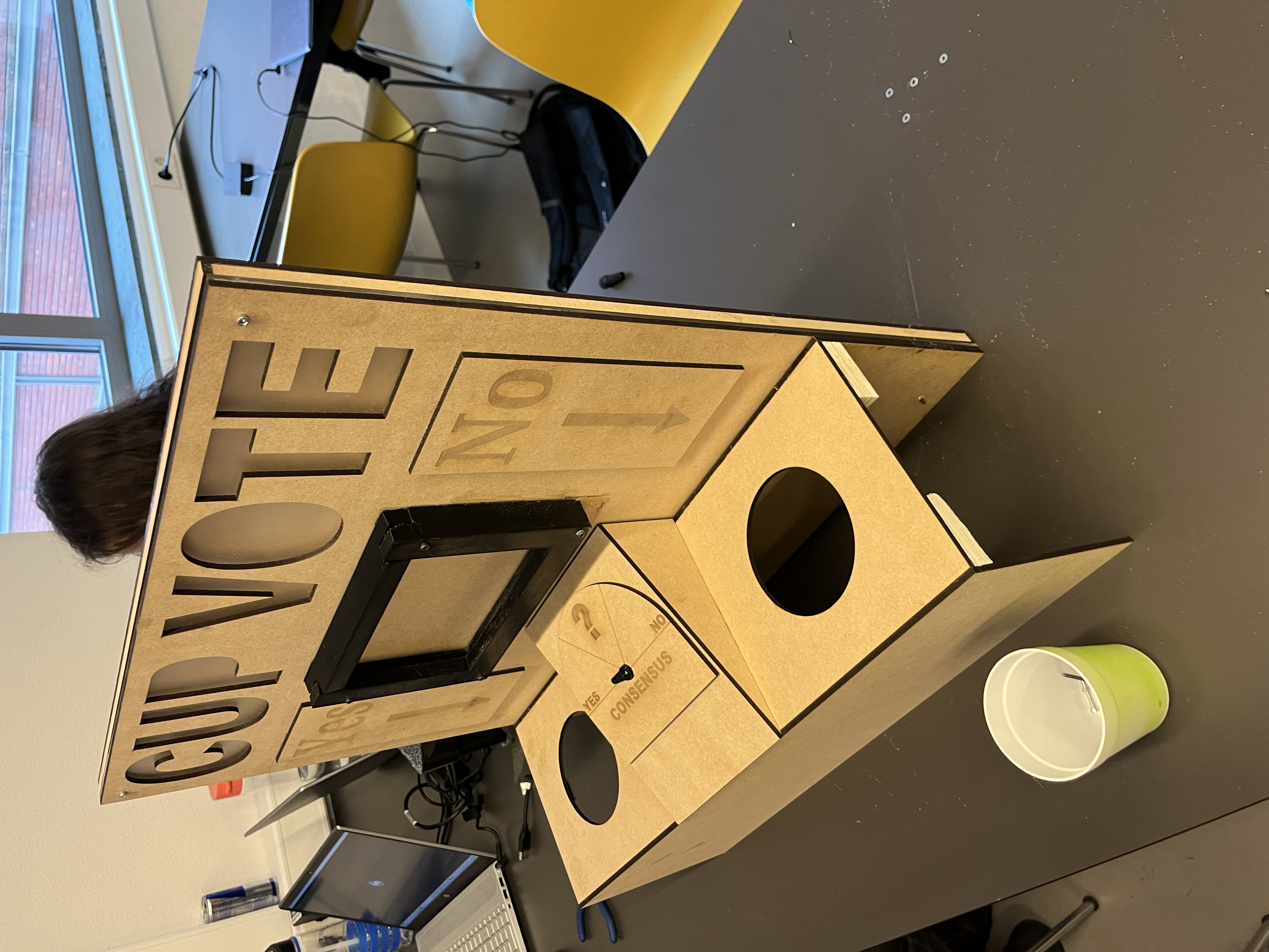
For sprint 2 we decided to switch up the design of the device from a cup-lend out machine to a more interactive cup deliver system. The device now contains a big board with the text 'Cup Vote' on it to instruct to the user on how to use the device. The cups can than be placed in either a 'yes' hole or a no 'hole'. The user decides to put the cup in yes or no hole depending on their answer to the sustainability question given on the tablet. This creates a few area's that need to be tested to ensure that the device works an is used by the users as intended. The area's that need to be tested are explained underneath.
The device that will be used for the user testing looks like the following:
Board
The board is the main factor in attracting the users attention to use the device. It also holds the text cup vote instructing the usage of the device, as well as the arrows to the holes with the text yes and no. That is why the headboard is one of if not the most essential part to the device and needs to be tested correctly. The following questions need to be answered to know if the device works as intended:
Question 1: 'Is the sentence Cup Vote clear enough on how the device needs to be used without having any explanation given to the user?'
Question 2: 'Is the question presented on the tablet readable enough and do the users even take the time to read the question before putting the cup in the box?'
Question 3: 'Are arrows needed to guide the user on where to put the cups?"
Answers:
The word Cup Vote is clear enough for the users to understand that they use the cups to vote without needing an explanation. When the tablet is there the tablet is big enough to grab the attention and makes it clear for the user on what he/she is reading. Arrows can be useful to guide the users on what to do with the cups. From the testing we can establish that adding arrows and the text "yes and no" on the headboard can be a good solution.
Box
The box where the cups will be placed in has a clear and easy to understand design, with two holes one for the answer yes and one for the answer no. The cup will be placed in either one depending on the answer that the user chooses.
Question 1: 'Is the cup easy to put in the right hole, and is it clear to the user which hole does what?'
Answer:
The hole is big enough to make disposing of the cup easy. With the testing device yes and no is put on the front of the box. What came from the testing is that adding the yes and no onto the headboard can make an impact on how easy it is to understand the box.
Overall design
To test the overall interaction with the device. The other students will try out the device without any knowledge or explanation about the device. In this way we can see a genuine reaction to the device and see how a real user would interact with the device. After the users have interacted with the device we ask them the following questions to get a better understanding about what is good about the device and what can still improve.
Question 1: 'Does the device look appealing to use?'
Question 2: 'Is the device clear on how to use it without any explanation?'
Question 3: 'Are the colors green and red correct to use?'
Answers:
From testing the device with several users we got the following answers to the questions:
The device is physically pleasing to the eye. The design is easy to understand for the most part. However to make throwing your cup in hole more clear one user suggested adding a picture of a hand throwing away a cup. Next to this adding arrows to the headboard to indicate to the holes can be a good addition.
The colors green and red would not be ideal to use, because it indicates a correct and wrong answer. One user gave the colour combination yellow and purple as suggestion.
Conclusion
Overall the feedback was positive. The device is interactive and fun to use. The device is also pretty understandable on how to use it without needing to have an explanation. However we can add elements like arrows onto the headboard and an explanation sticker to improve the useability of the design. Also the colors green and red invokes a feeling of correct and wrong, so this can be changed. This to make the selection of an answer feel more neutral. Also the box that is put underneath the box to catch the cups needs to have a soft bottom to help dampen sound when the cups are dropped into the device.
Sprint 3
IR-sensor mounts
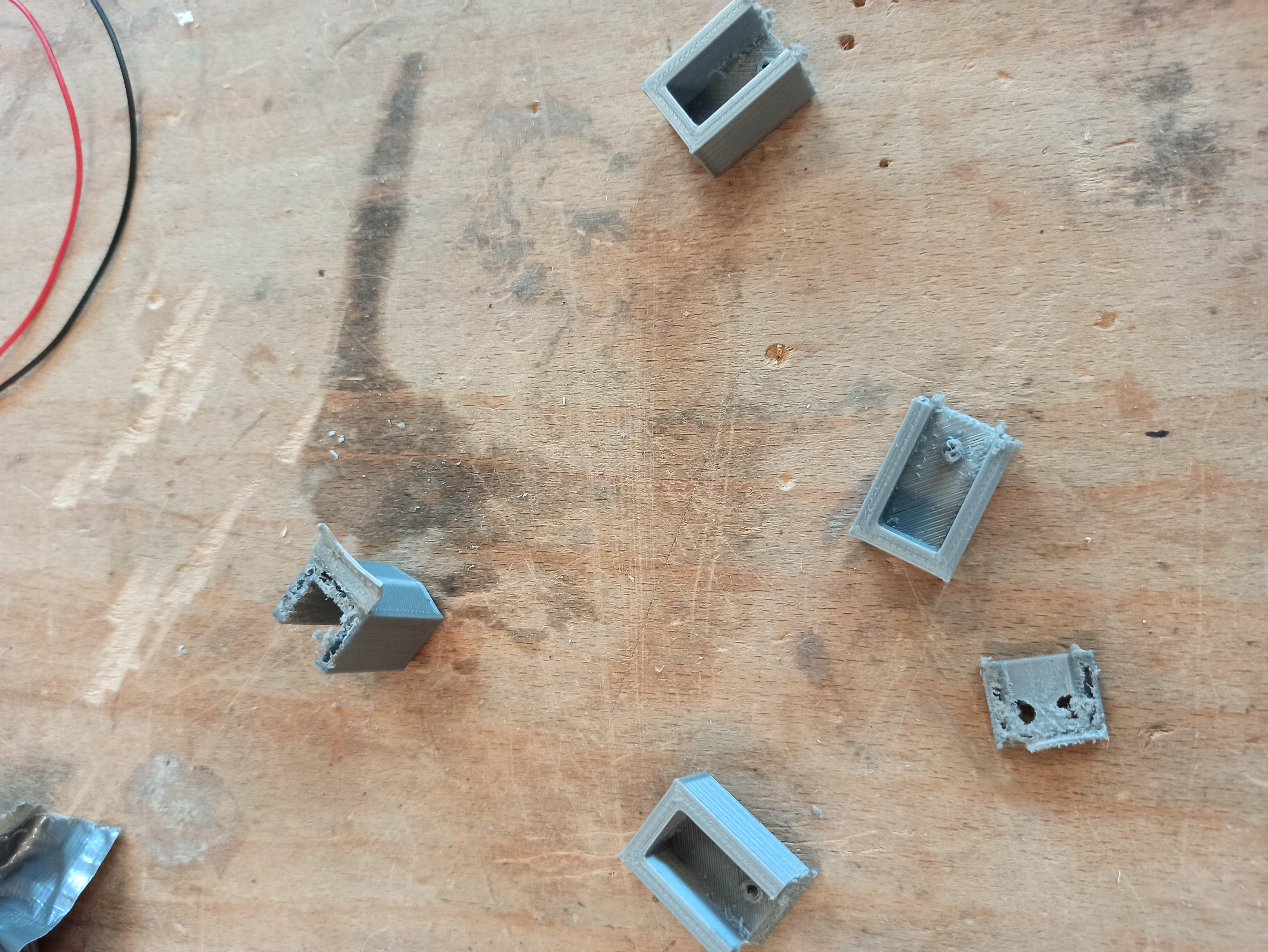
To mount the IR sensors we have 3D printed the brackets. For this we did not use a high infill density / quality, since these brackets are mounted in the device.
YES/NO Meter
This sprint we have improved on the YES/NO meter, we will make this out of wood now. For this we have also made a frame on which it will be placed on the device and a servo bracket.
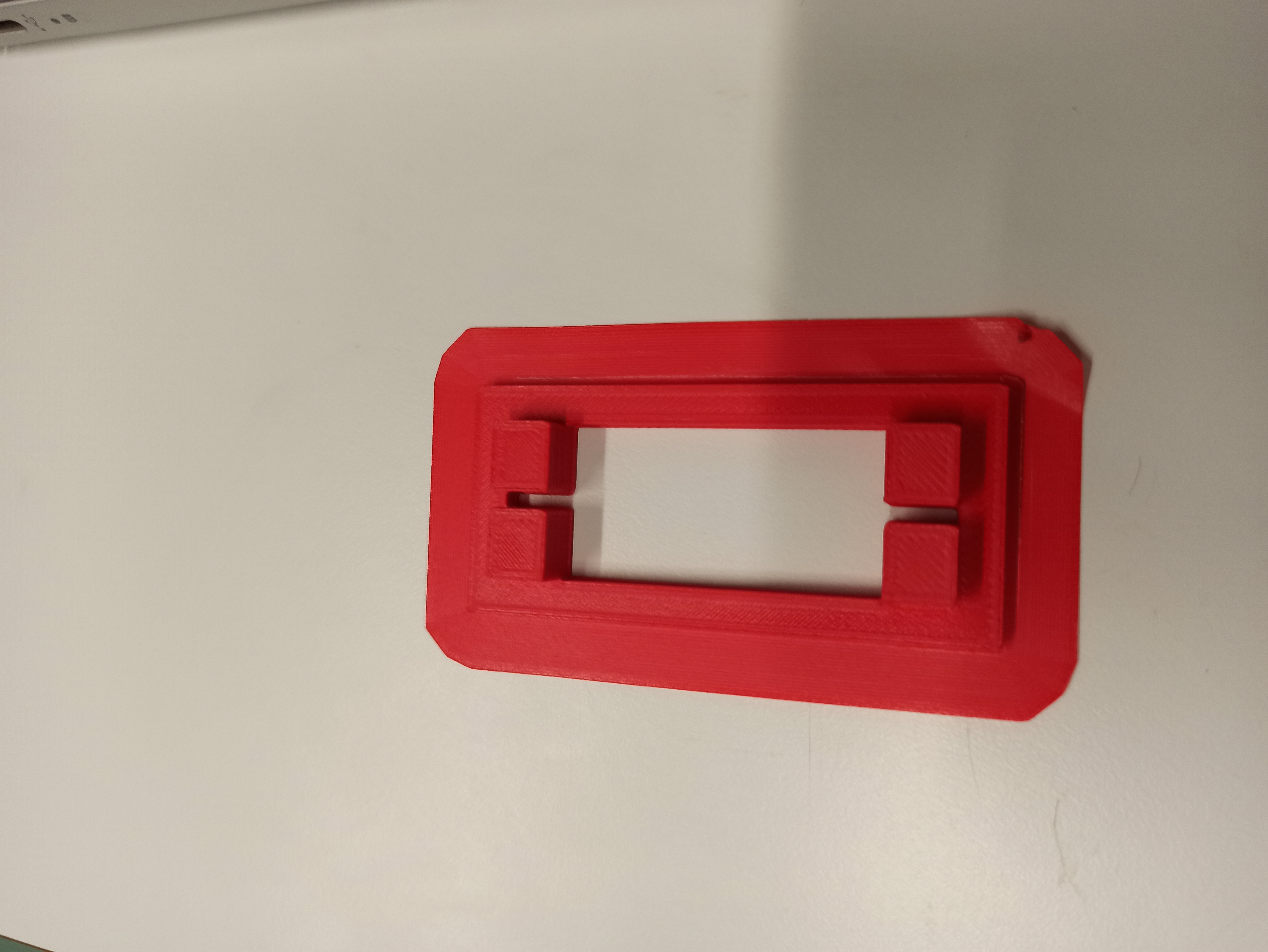
Servo Bracket
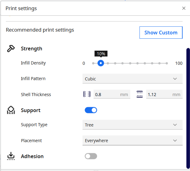
For the servo bracket we have made a 3D design. To print this bracket we have made use of the following settings on the 3D printer:

Here we took the draft quality, since it did not have to be pretty, since it is not shown to the user. We also did an infill density of 100%, since we wanted to screw it into the servo. Luckily the print went fine on the first try. And we are left with the design as can be seen below.
Meter frame
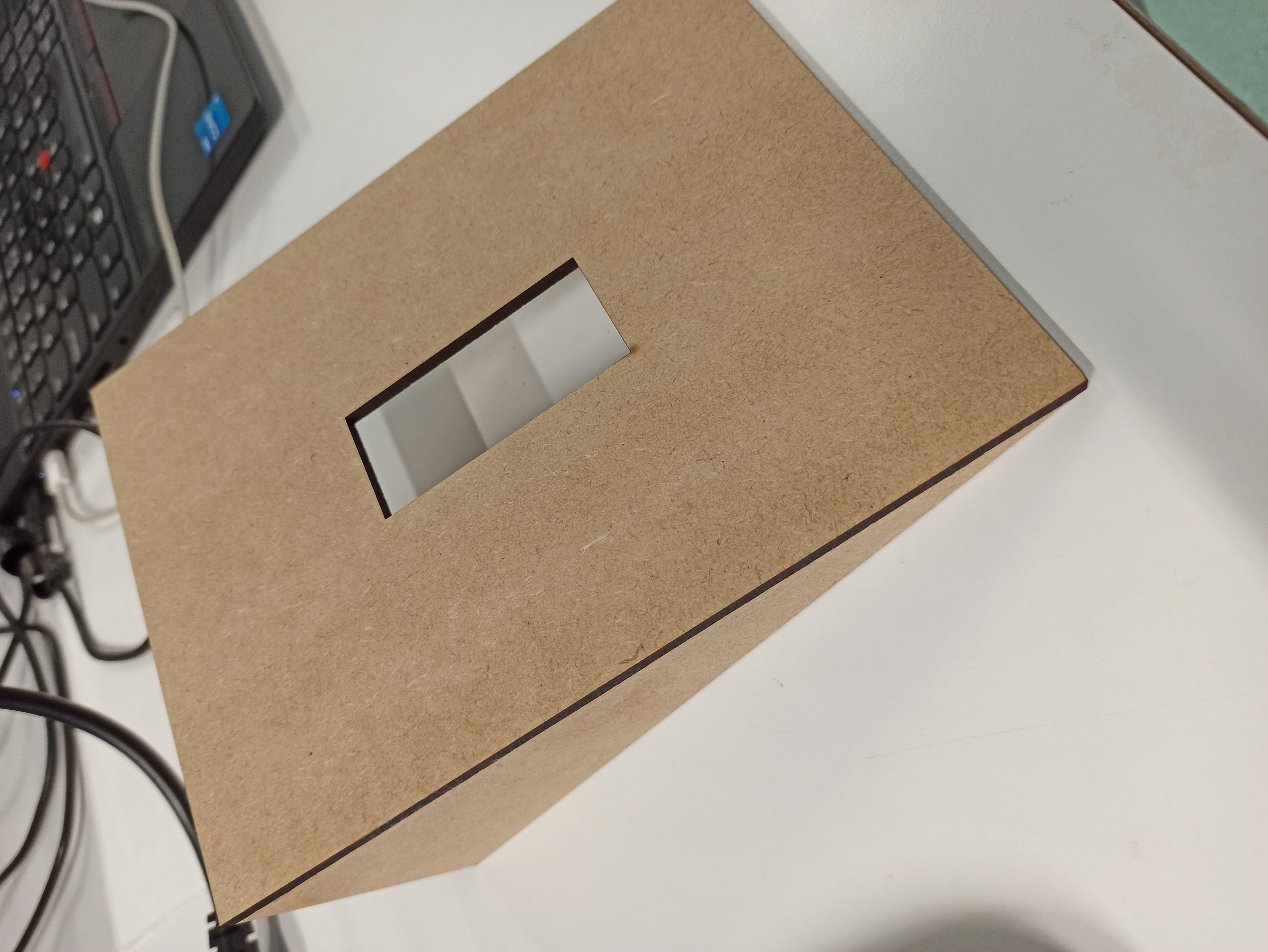
For the meter frame we have used MDF again. This was quite a simple design to make with the laser cutter. The settings we used are the standard settings for MDF, which we mentioned previously.
The end result looks like this:
Meter Background
The meter background will be made of MDF as well. But in addition to just cutting the frame, we will also engrave the YES/NO in the wood.
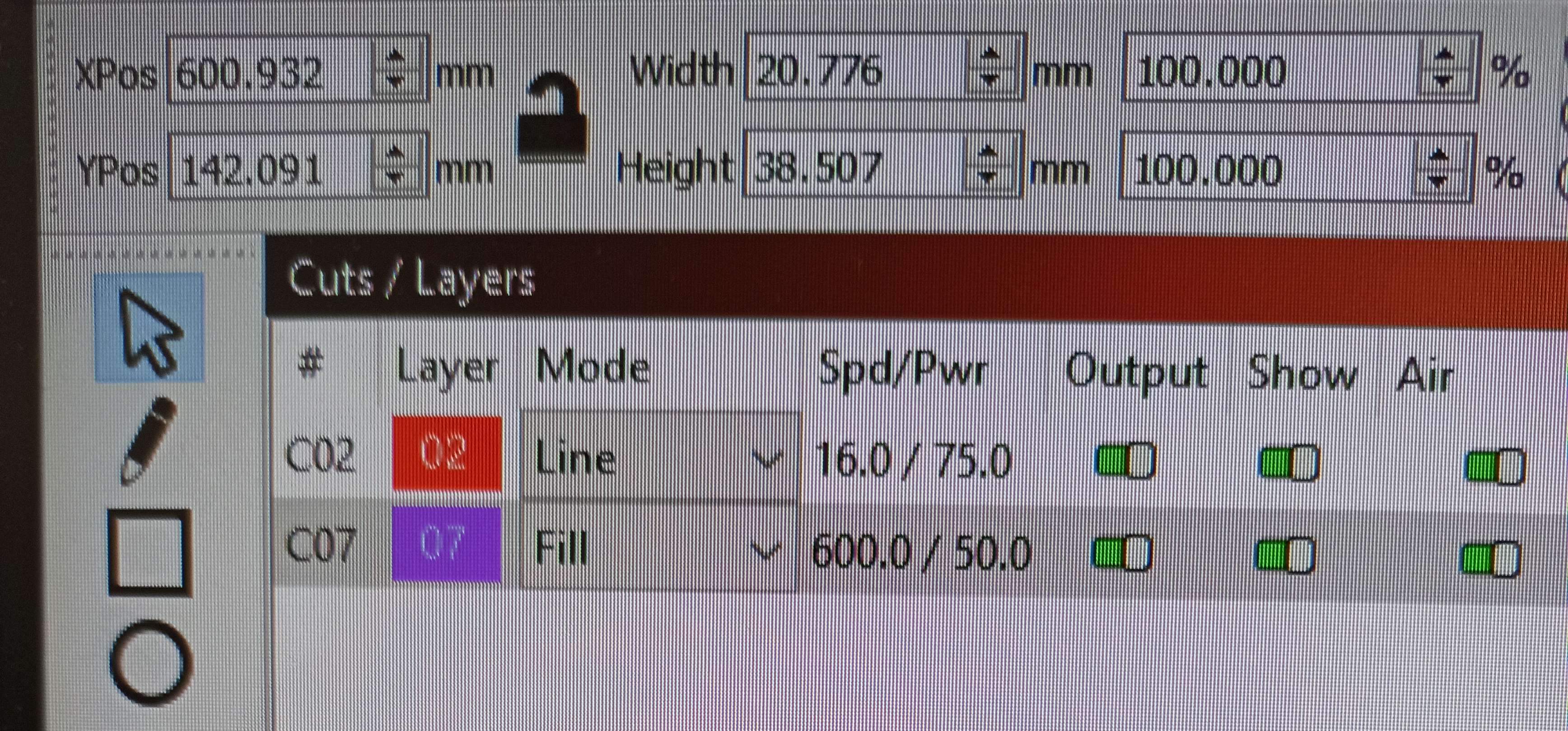
To laser engrave we have used the following settings. These were based off preset settings available at the Makers Lab. Due to the high speed and lower power, it engraves instead of cutting through the wood.
Result
Afterwards we are left with the following result.
YES/NO Sign
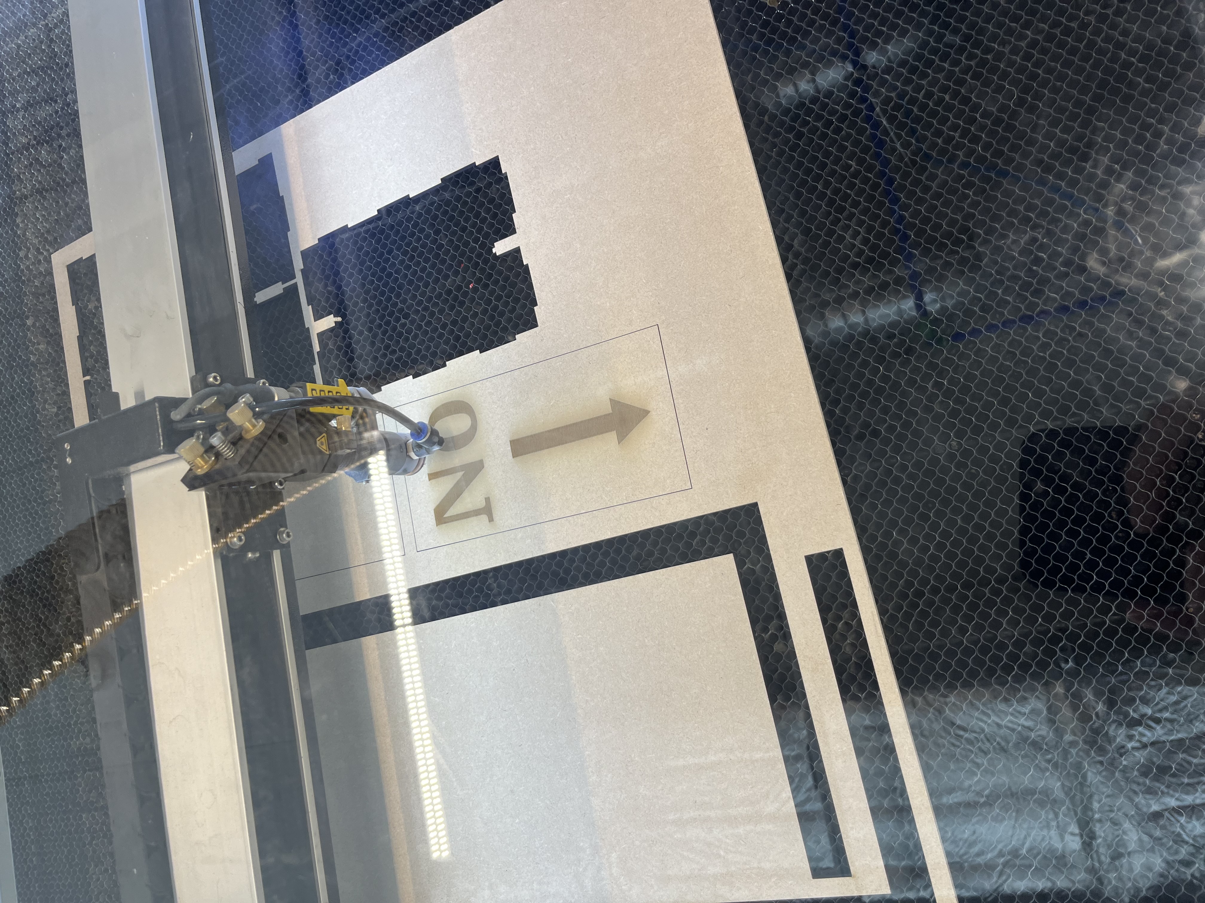
To create the words yes & no onto the board, we first going to engrave the words separately onto two pieces of wood with the length of 20 cm's and a width of 10 cm. This ensures that there is enough space for the words to be placed on it and it also leaves enough space for the arrows to be placed underneath the words. The words yes and no will be engraved by the use of laser engraving.
Arrow
To create the arrow that will be placed onto the headboard, we first are going to engrave the arrow onto the two pieces of wood with a length of 20 cm's and a width of 10 cm. The arrow which has a size of 10 cm's long and a width of 3 cm will be engraved underneath the words yes and no.
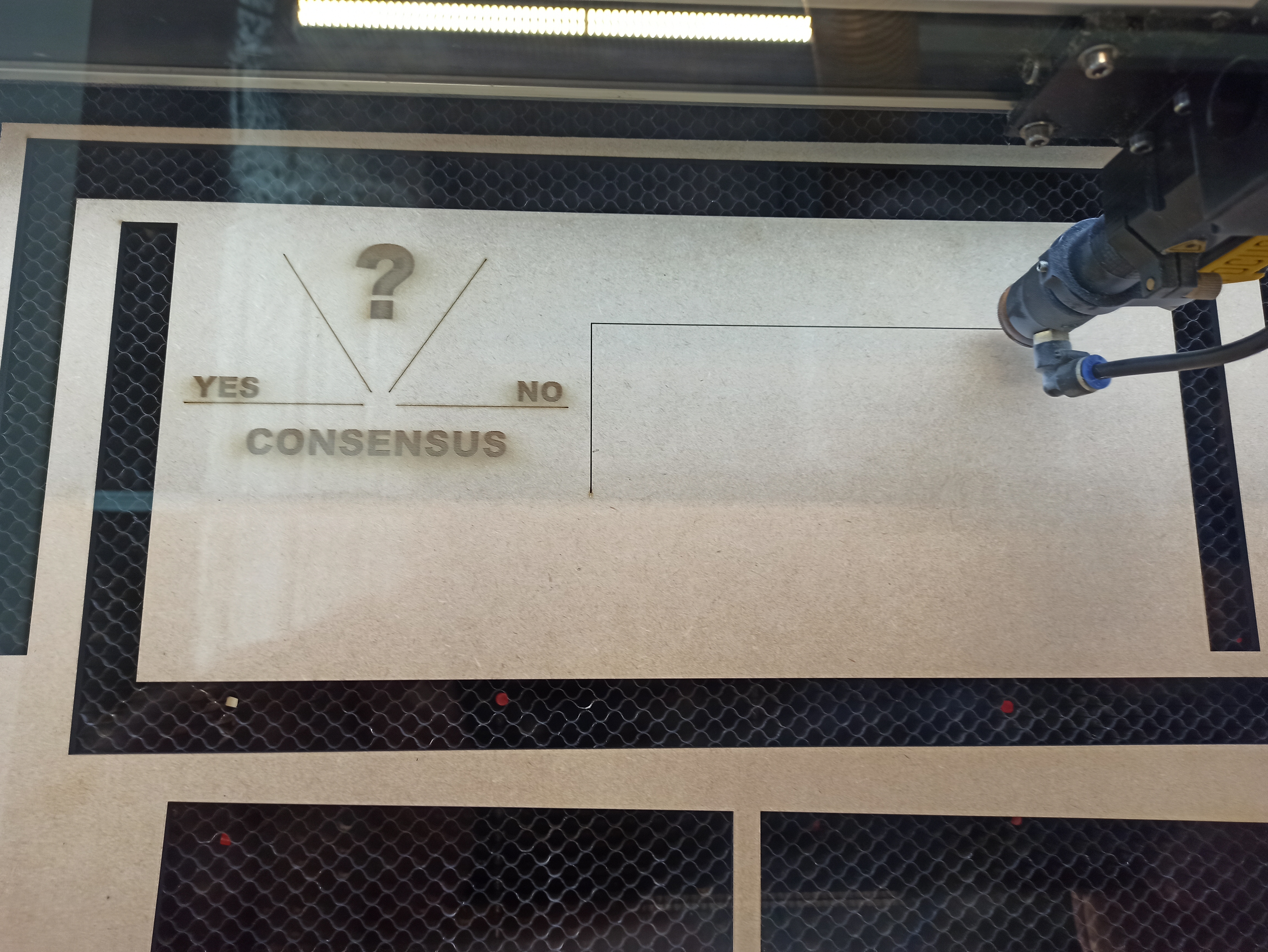
The settings used for the laser cutting and engraving is as follows:
The process of the laser cutting and engraving is documented here. Through the use of photo's the different stages of the creating process is highlighted.
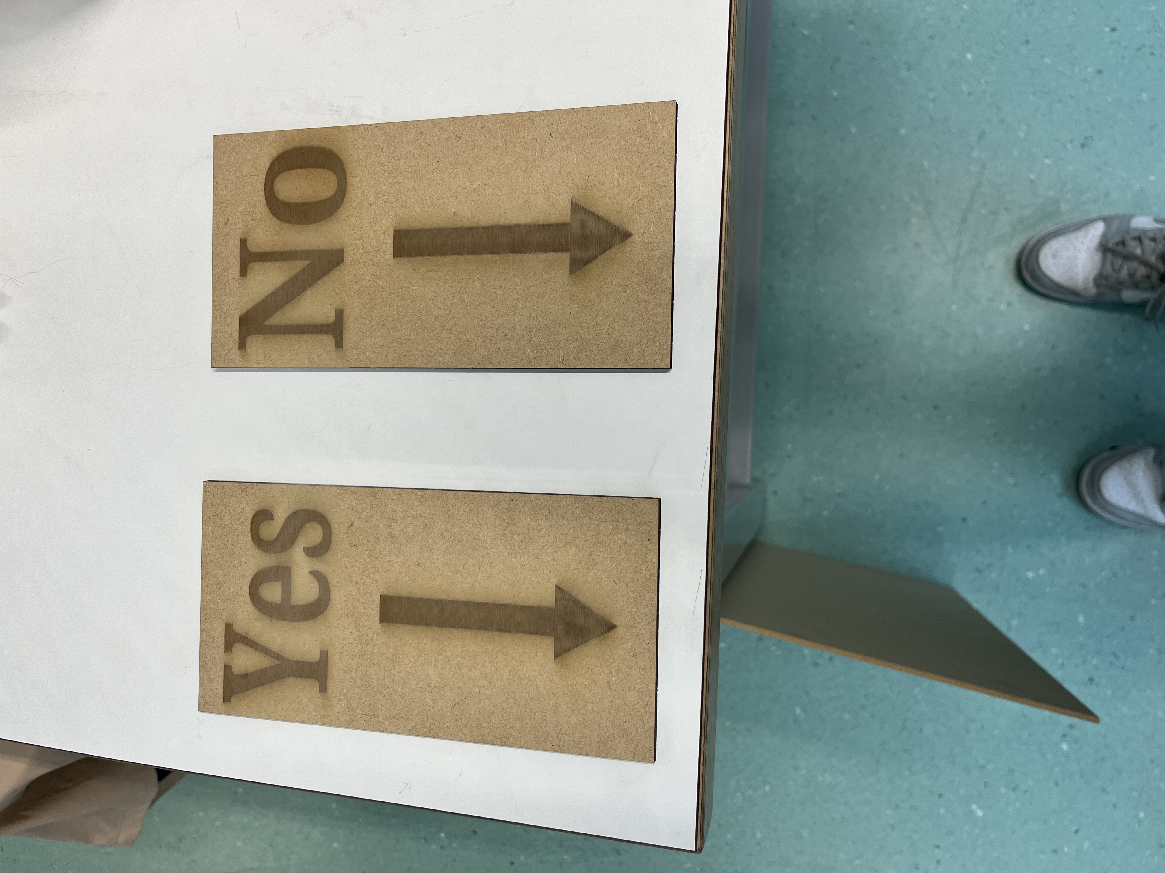
With the smaller boards now made we can attach them to the main headboard, creating a clear indication to the user which hole means what.
Light diffusion panel
To make the light behind the sign nicer, the task was to create a simple plexiglass panel that would fit behind the current sign. This seemed simple but the settings for cutting on plexiglass were a bit more complicated than imagined.
The settings shown above should have been valid for the material we used, I personally suspect that the focusing mechanism for the laser machine had trouble determining the distance through the acrylic. We were told to remove the foil covering the plate but this might have been the wrong thing to do. The plate was lightly damaged and not cut fully in the process.
On a second run a day later we managed to get the machine working, the issue was in the fact that the machine could not correctly determine the focus on a clear plate. The fix used was given by one of the teachers there which included putting a small piece of paper on the plate and then running the focus system. This solved the issue of the light refracting and the light not cutting the plate.
Collection box
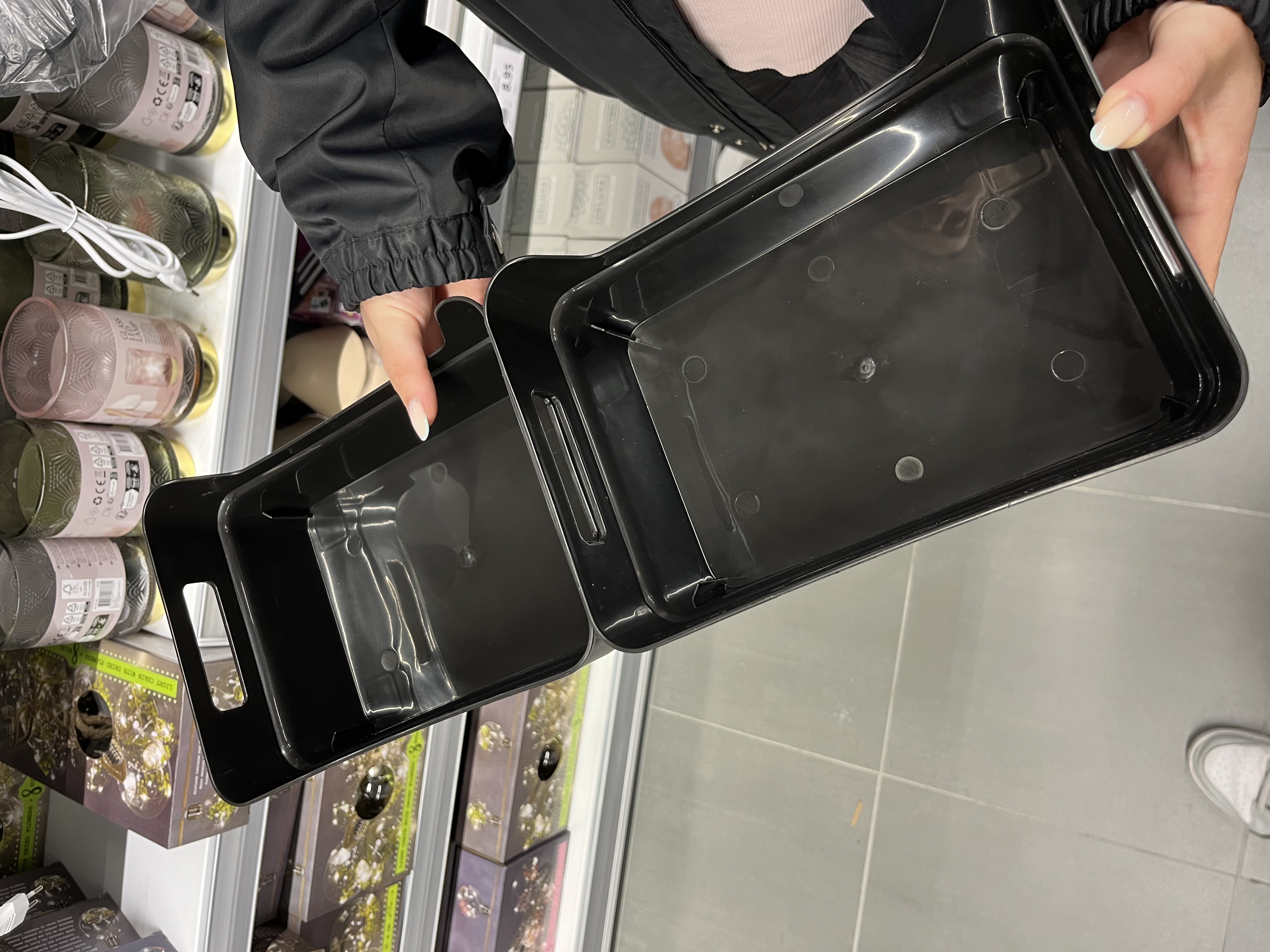
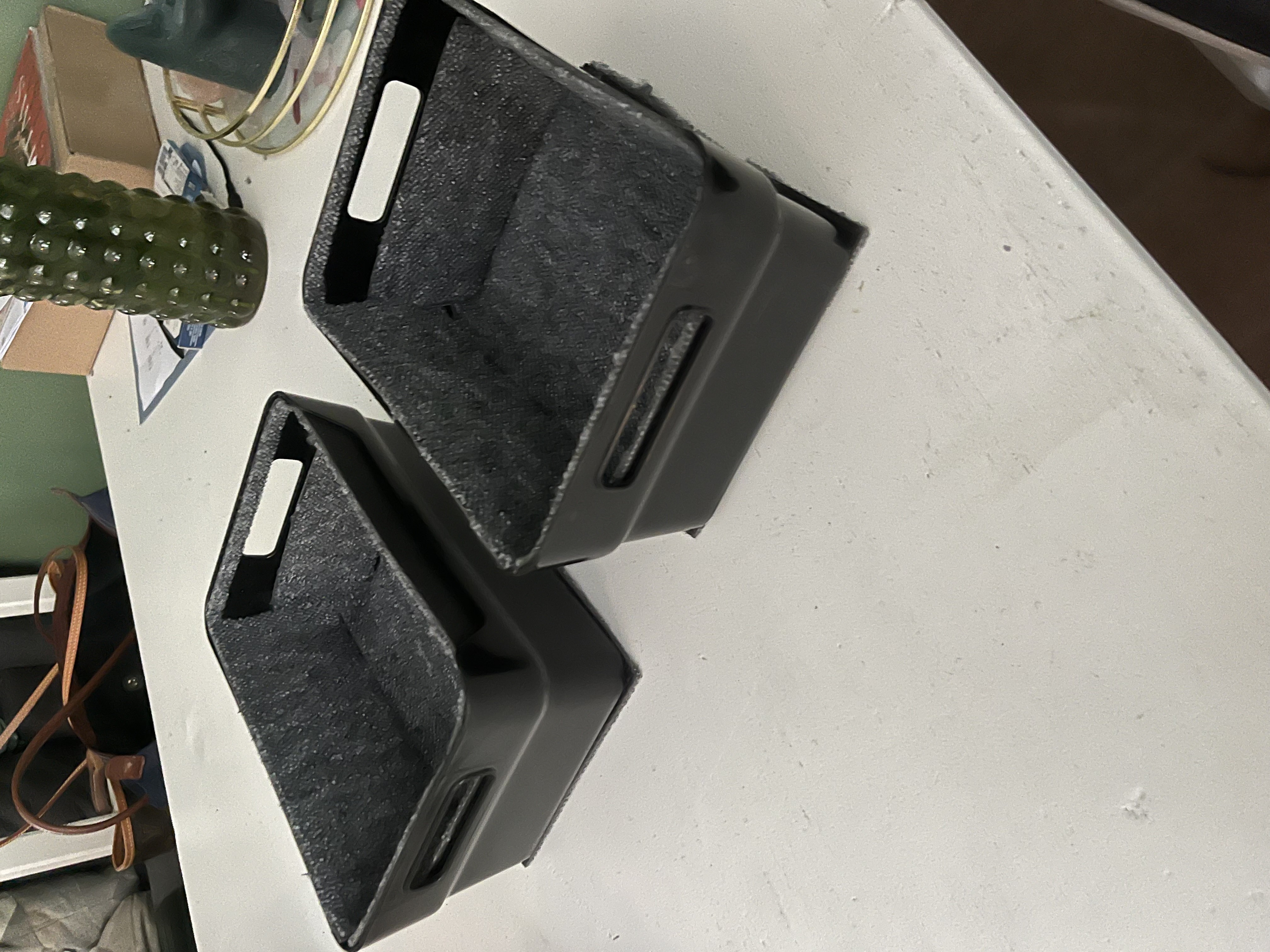
Underneath the device there needs to be a box that collects the used cups. The device has a length of 55 centimeter a width of 18 centimeter and a height of 15 centimeter. To find one box with these exact diameters was almost impossible. We went to Praxis, Action and searched online on multiple website's, but we couldn't find a box with the correct sizing. In the end we went with two boxes with the following sizes: A length of 24 centimeters each, a width of 17 centimeter and a height of 10 centimeter each. The two boxes can be placed underneath the two holes functioning the same as if there was one big box.
The boxes were bought at action and looked like this at the start:
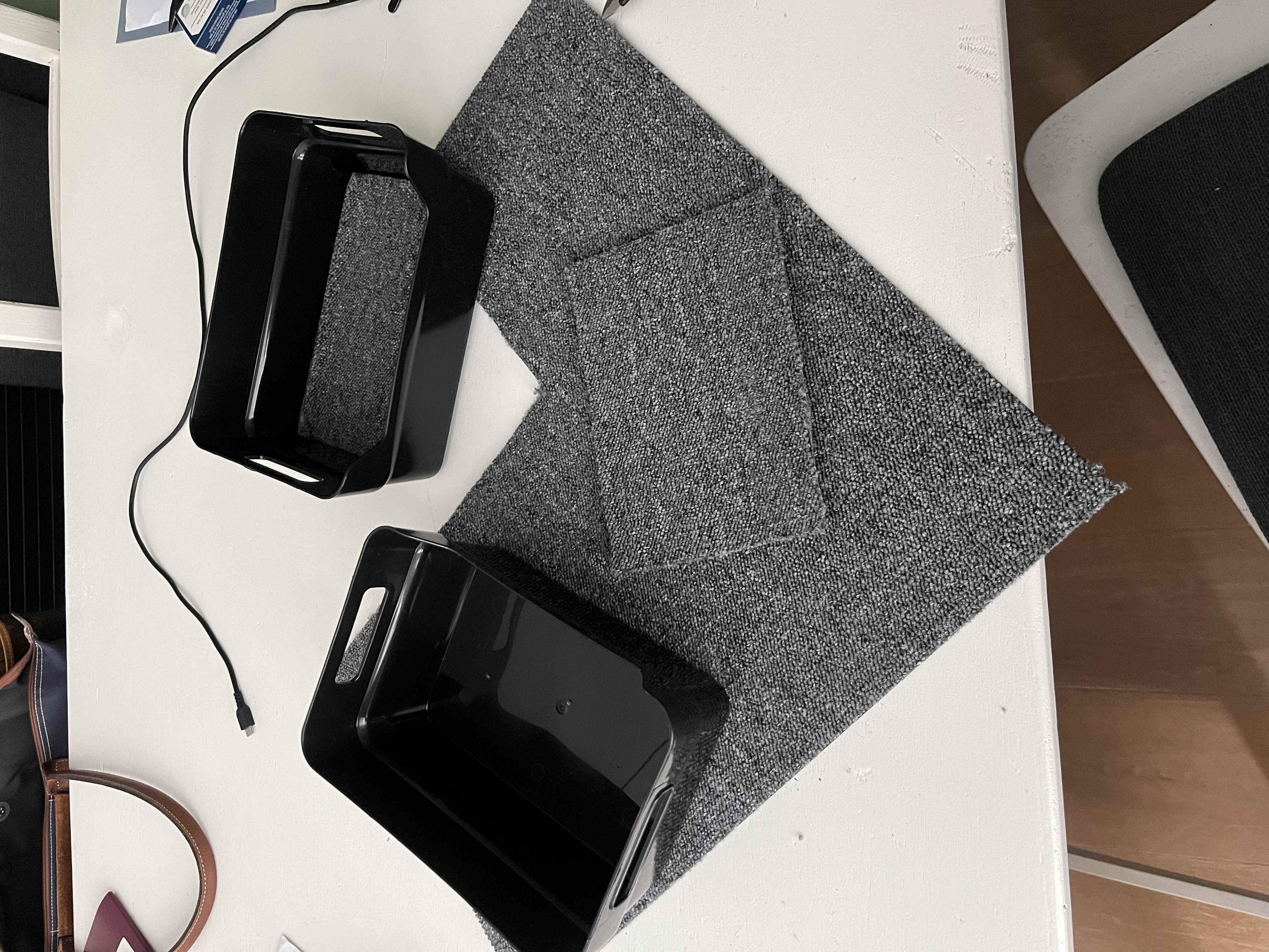
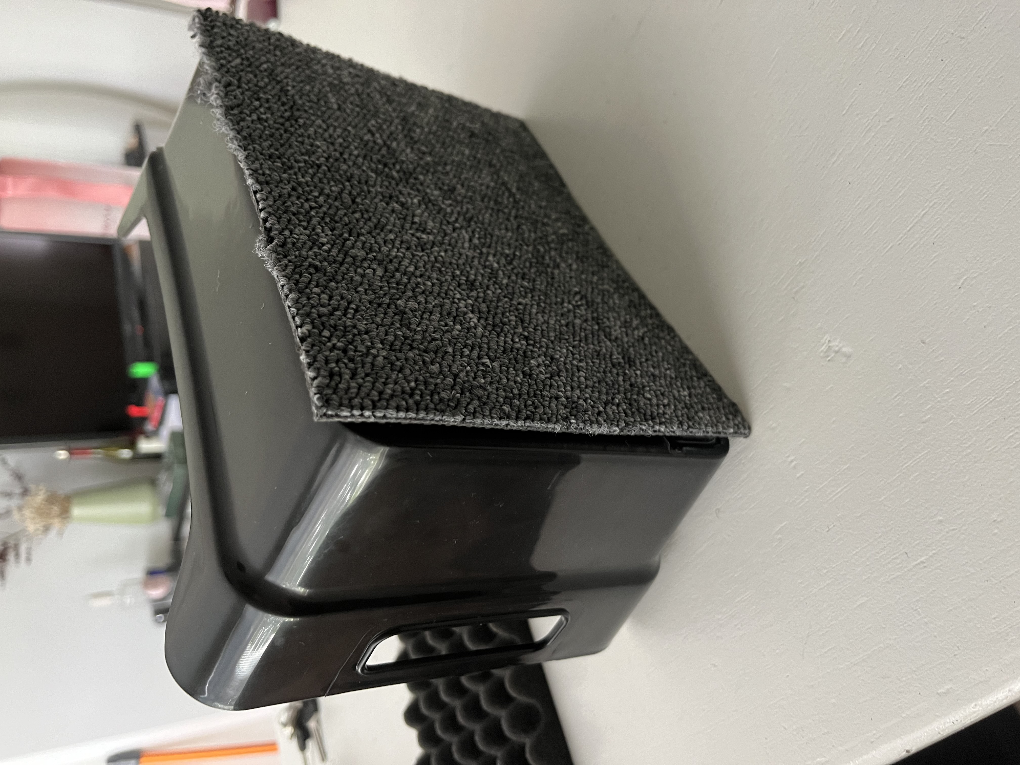
The box is made of plastic and leaving it just like this would still make too much noise when a cup is being dropped into the box. To dampen the sound we bought a softer fabric to be placed in the box. The fabric with the first layer in the box looked like this:
The boxes will be placed on a hard surface, so the bounce back of the cup will still make quite some noise. To counter this we also added the fabric on the bottom of the box, with the rest of the fabric spread out on the other parts of the box to dampen the sound the final two boxes came out looking like the following.
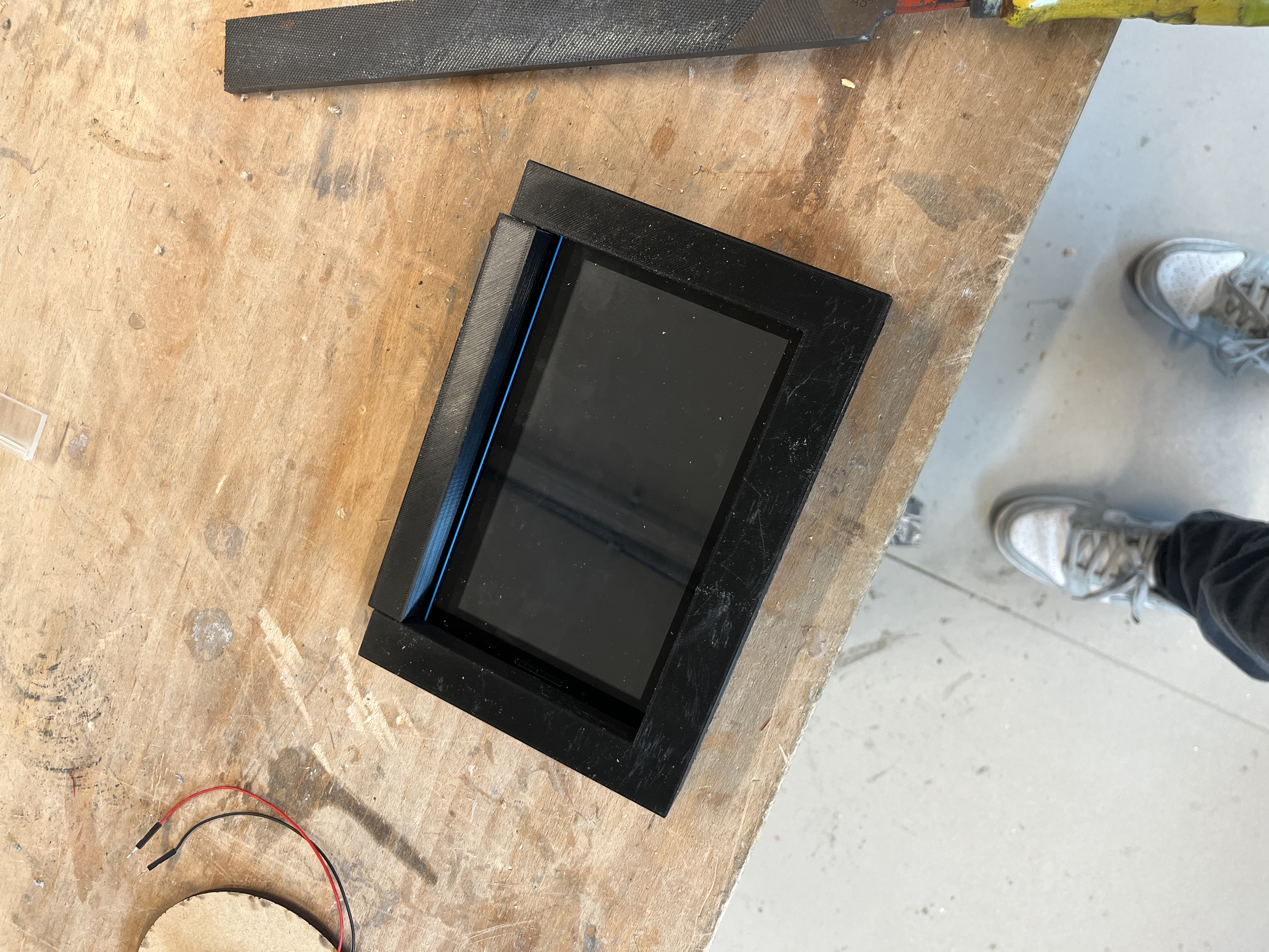
Tablet Frame
To create the holder/frame for the tablet we start by importing the .stl file we created in Tinkercad. With the .stl file imported we open the file in Cura Ultimaker to get a .UTF file. We can now eject the file onto and usb and put the usb into the 3D printer starting the print. This print is a big one using 352 grams and taking 19 hours and 57 minutes to print out. The .stl file and utf files are down here:
The settings used are the same as we used for the 3d printed letter. The infill at 100%, the quality on draft 0.2mm, the zig zag infill and adhesion on. The fabric used is standard PLA.
Prototype assembly
After making most of the individual parts, another important step is to finally attach all the hardware. This includes making brackets for the IR sensors and holes so that the power can be properly connected.
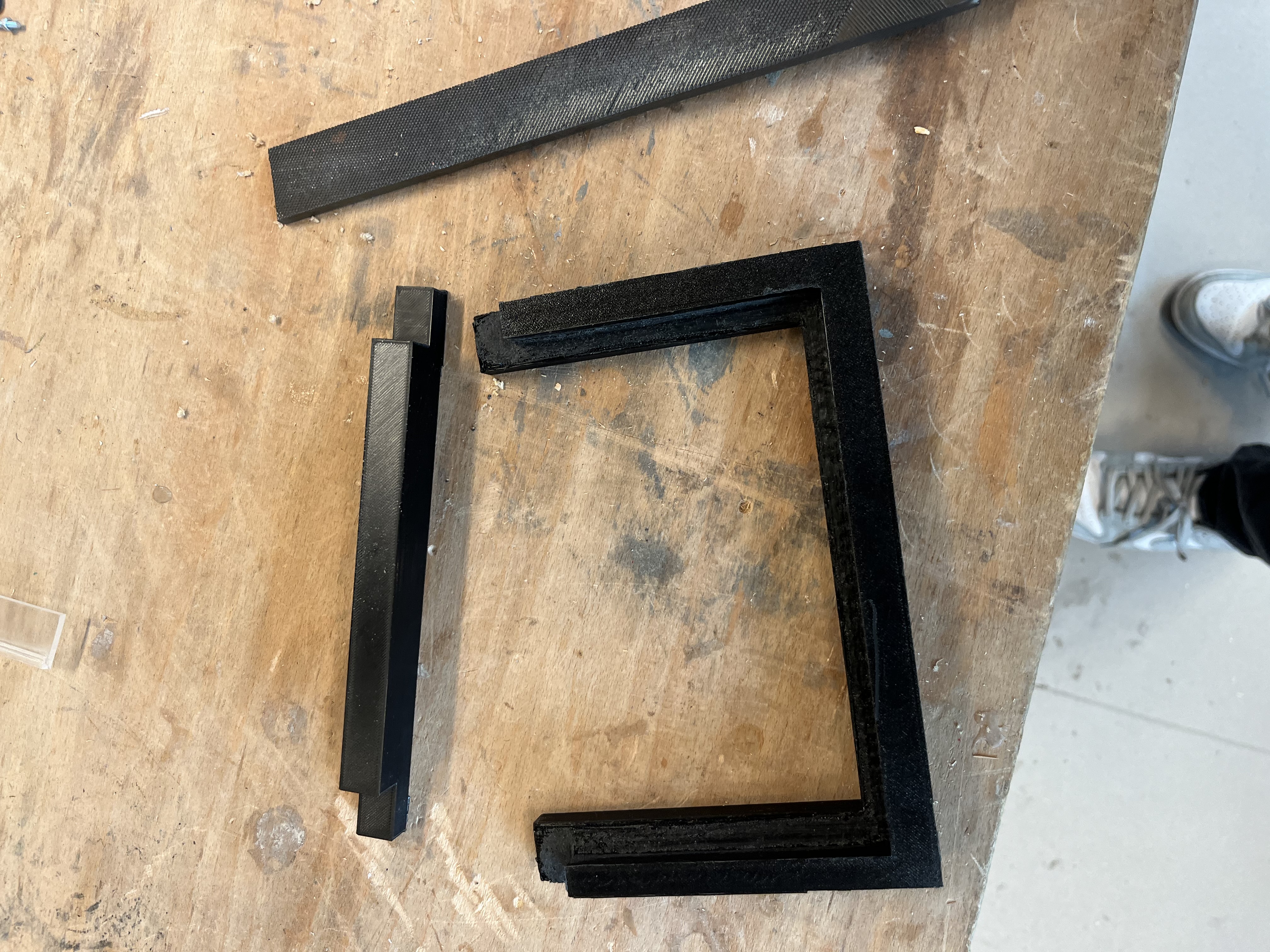
We quickly noticed that the holes in the brackets where a bit too small, so the cable would not fit through, therefore we have cut the ends off, since these were not needed to hold the sensors. They do not look as nice anymore, but are still usable for holding the sensors steady.
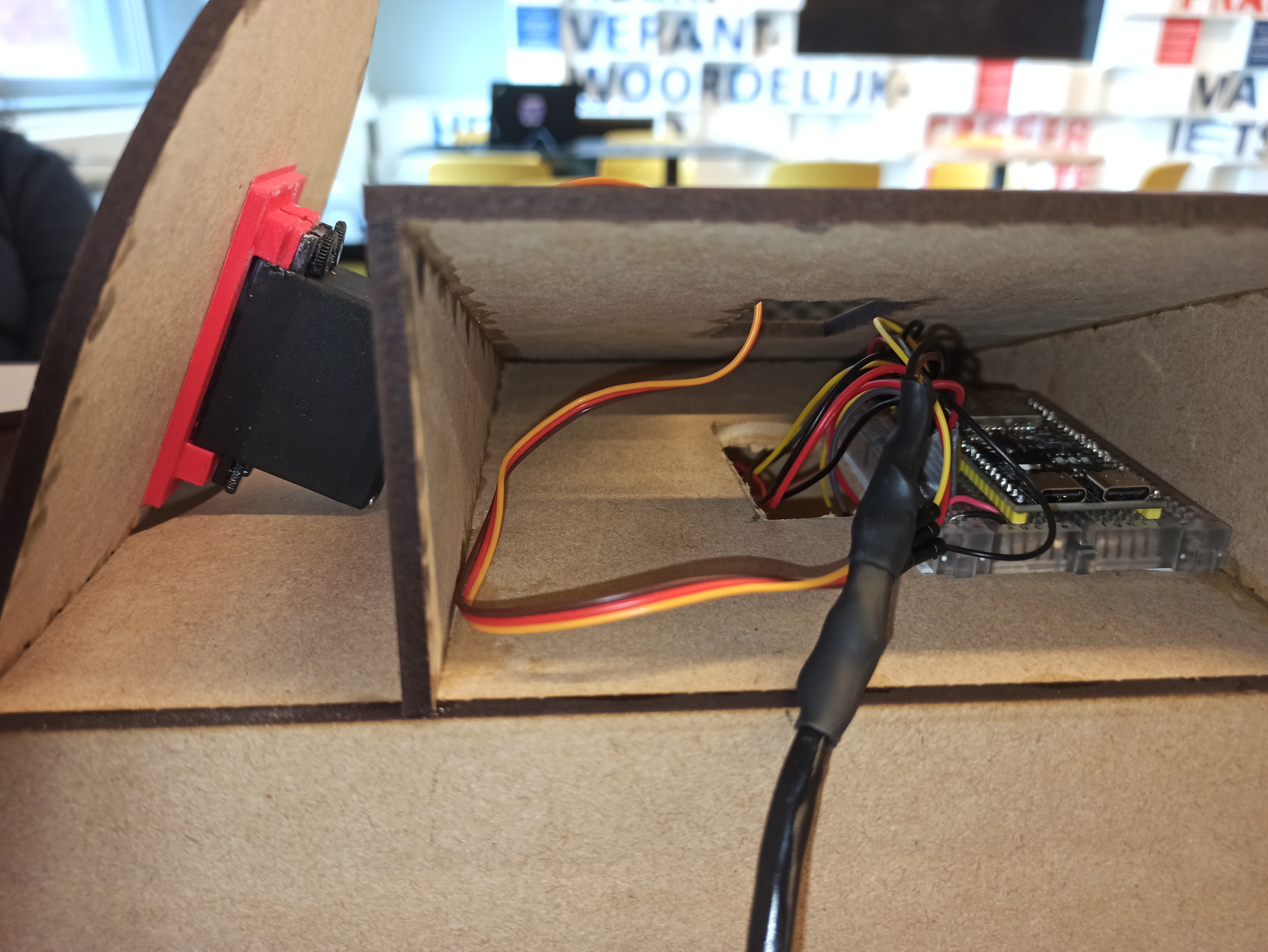
After glueing these brackets on, the IR sensor were put in and the wires connected to the microcontroller.
Here the servo is connected. We simply used a tiny breadboard to connect everything. The cable for the LED strip is connected as well, this will go through a tiny hole in the board, along with the power cable.
Additionally we also wanted to add a backboard onto the board to make the led lights stand out more. The process of assembling the device started with cutting the new backboard through the use of laser cutting. This is simply a square of 55cmx55cm, with pieces of 1cm thick glued on
After the backboard was cut, the side pieces were placed onto the edges to make it that when the board is placed against the headboard, it leaves a bit of space in between for the cables and the led light to shine.
With the sides attached we could now make the holes on the right placed to attach it to the headboard. This process took a while but after it was all finished it looked like the following:
Now with the backboard attached we needed to make sure that all the embedded elements still work as intended. We screwed the backboard tight enough to be hold up but also to leave enough space for all the cables to stay working. In the end our final product looks like this.