Concept & Design
With this project the idea is to create a product to get attention for the Sustainable Developement Goals (SDG). The Green Office of HvA (GO HvA) currently does this with events and stations. One of these installations is there cup lending station, promoting reusing cups even when you forget yours.
Now that is the idea of this project? In short, getting attention for the SDGs. Longer version is improving the cup hand-in display so that the usage of that stand can be shown and to try and inspire people to be more sustainable. How were inspiring people is still up for questioning. The main idea for this is to use one these things for that.
- Informing people.
- Make people think about sustainability
- And lastly allowing them to lend cups.
This page will be divided in Minimum Viable Products for all three sprints.
Note
We have changed our concept a lot during the project duration. Therefore we did not strictly complete every point mentioned in the first two MVP's. Since we also changed things during a sprint.
Sprint 1
Minimum Viable Product
Date: 18-04-24
This contains the main goals for Sprint 1
1.0 Embedded Device
- Can transmit data to backend
- Point 1 is done with HTTP requests
- Must be able to forward RFID reader value
- Must be able to turn LEDs on and off
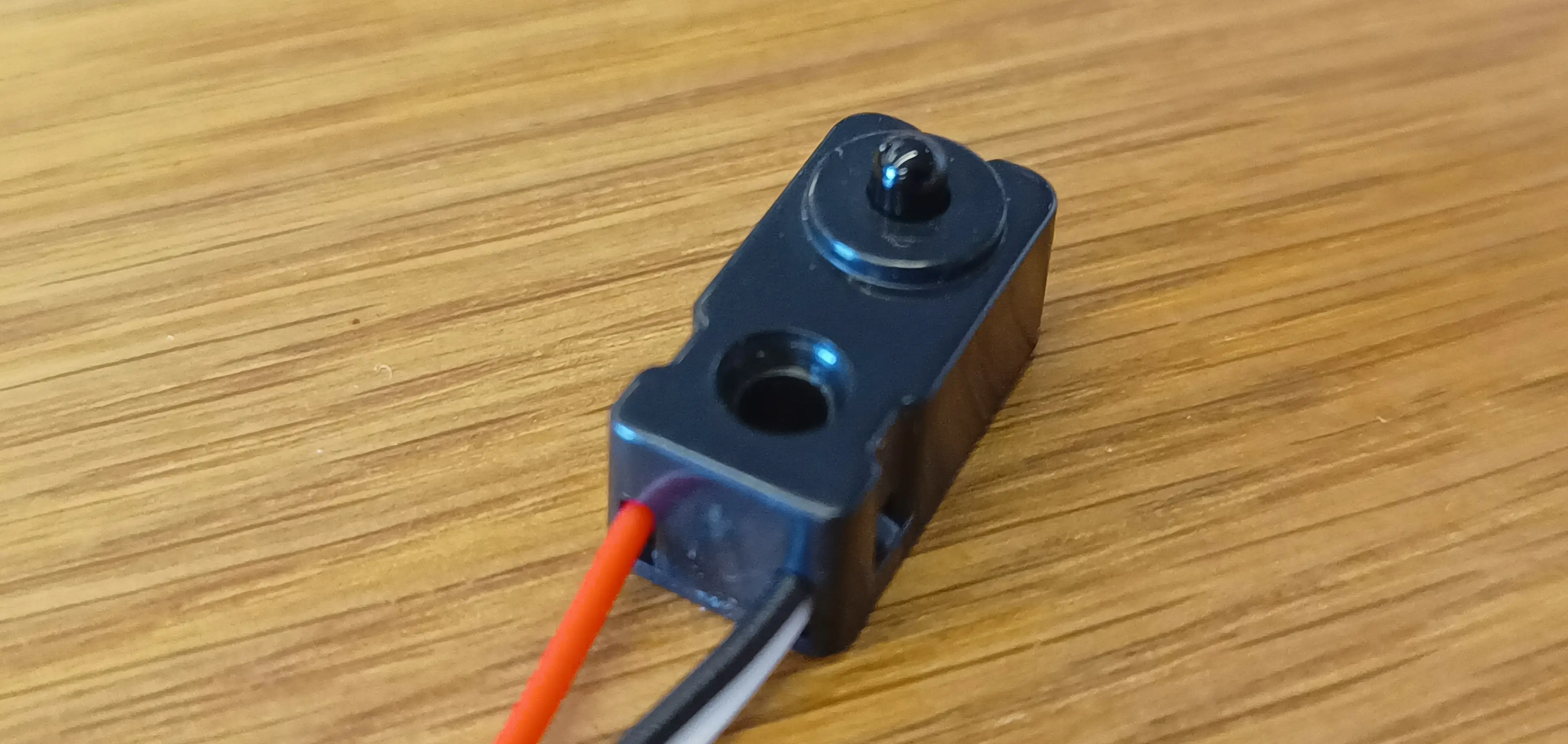
- Must be able to read laser sensors (is there a cup?)
- Must be able to display status messages on LCD
- Documentation on module, hardware & software
2.0 Website
- Minimally secured, owner should not be able to break it
- Has Owner page
- Can communicate with database
- Owner page contains: cup usage data
- Documentation on module, software
3.0 Physical product
- Contains holes for the sensors
- Contains holes for LEDs above the cup(s)
- Contains an enclosed module for the RFID reader and the Wemos
- Contains a location where the LCD display can be read
- Consists of a shelf with a 90-degree angle
- One module contains the Wemos and RFID reader
- Must have a place where the cup(s) can stand
- Wiring is hidden away
- Must have a readable LCD
- Wiring tree 5V
- Wemos powered via USB adapter
- Documentation of the structure (contains explanations for construction and connection of the electronics. Additionally, future recommendations are included here)
Concepts
For the physical design there where multiple brainstorming sessions giving ideas of how the design could work. Below are the images resulting of this with a description of what it is.
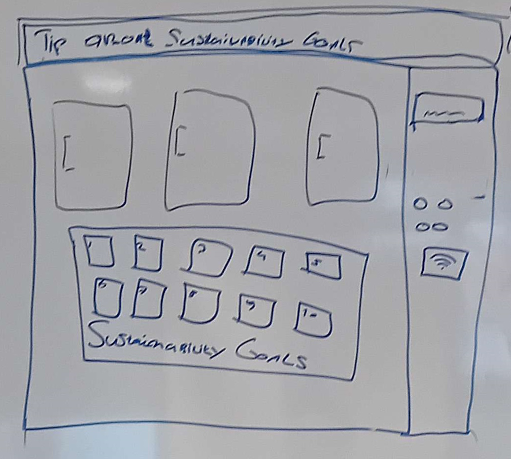
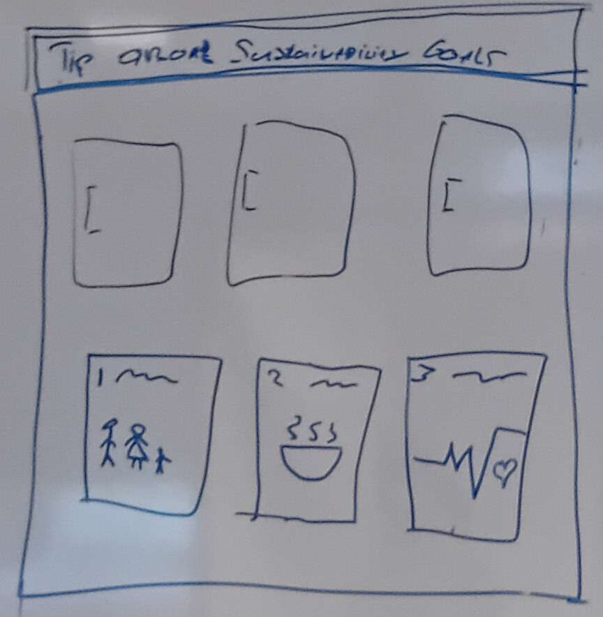
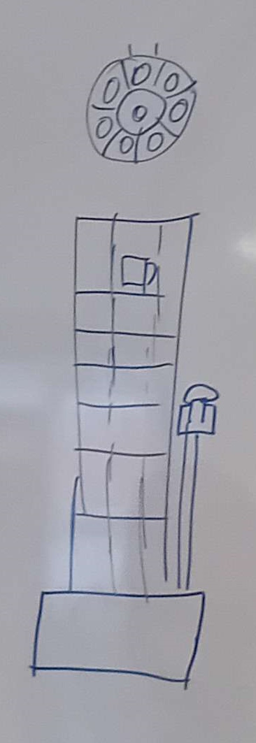
Vending machine - static doors
One idea we had was to create a vending machine were each cup is linked to one of the seventeen Sustainable Development Goals (SDGs). The cups are locked behind a door. When you want a cup, you can choose one of the goals to receive the associated cup and information about that goal. Sustainability goals can be printed on the doors or even shown separately like with the first image. Above all these doors is a screen where information about the sustainability goal can be shown.
Vending machine - moving
Instead of using different doors, we could also use a moving opening to only allow users to pick up one cup. Another way is to have a rotating tower where users can only interaction with the side where the users interact with the screen.
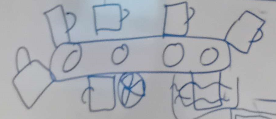
Conveyor belt
Another idea is to place to cups on a conveyor belt. Where the user can get a cup as it moves past them. When a cup comes to the end of the belt, it could be washed. Once clean it will be placed at the start of the belt again.
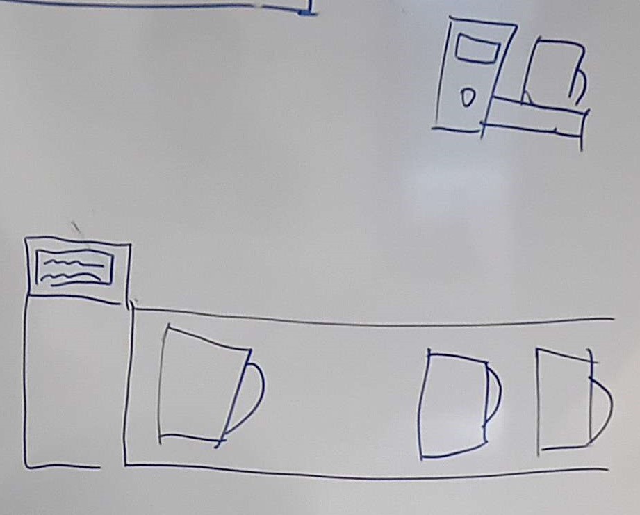
Plank
One of the simpler ideas is to place all the cups next to each other. And show the same message on the screen for each cup.
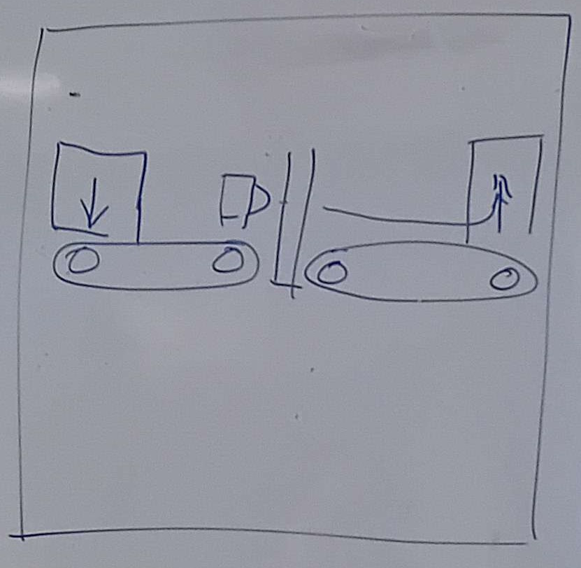
Sensor attachment
No matter what design this project will use, all need to have a way of attaching the sensors. Given the sensors themselves have mounting holes and are rectangles.
The first design is a slide in design. allowing sensors to be put in a hole with the cup slightly lowered. Within the image this is held by a bolt but this could be friction or any other way of mounting them.
The second idea was to mount the sensors on wooden rods on walls between the cups. This would hold the sensors in place and would be simpeler than the idea above this. This wood should be the size of the sensor's mounting hole making a pressure fit, or being able to hold it in place with a bit of glue.
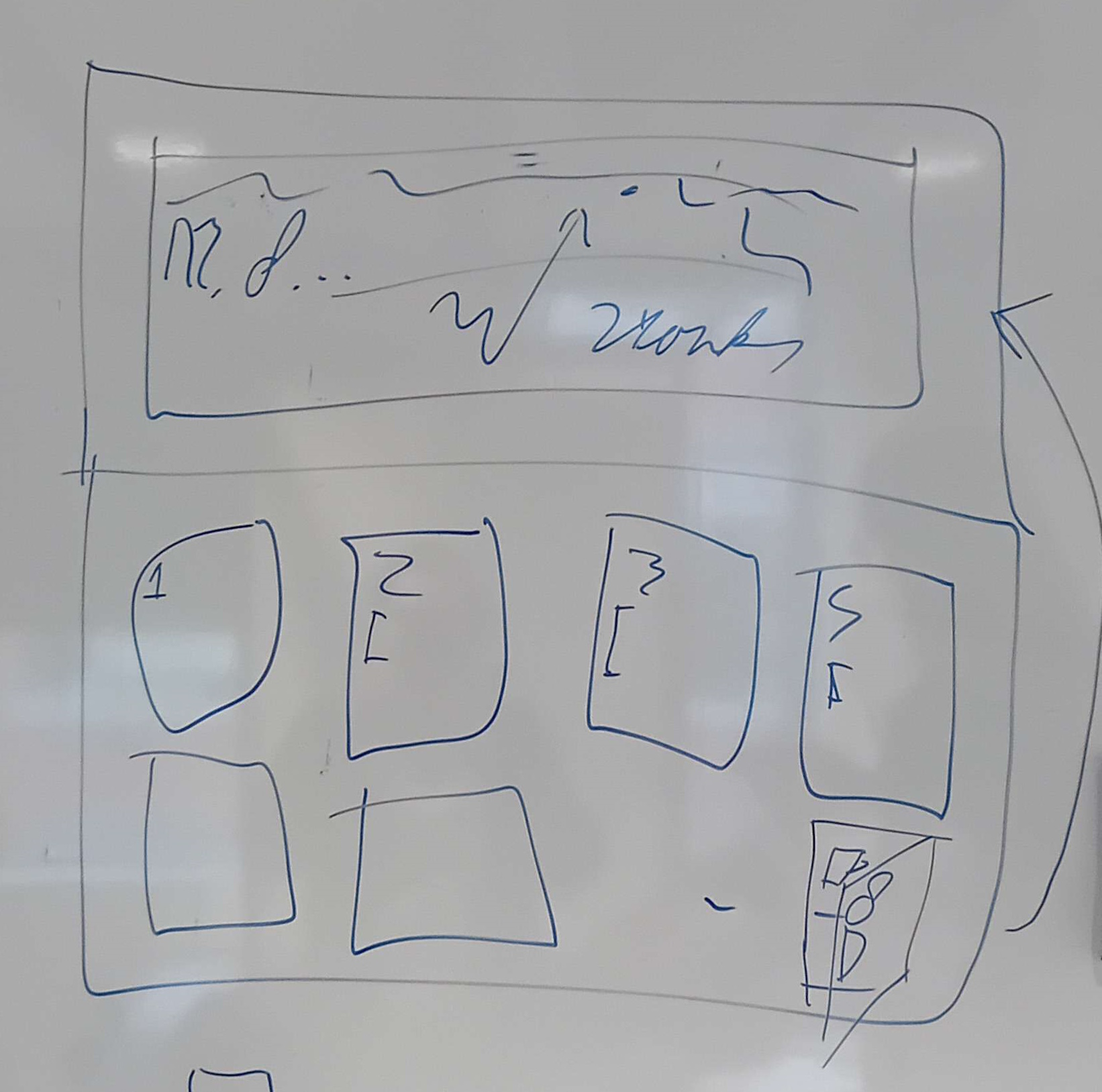
Designs
The prototypes there designs are shown below. How there made with what method is shown on the Create & Test page.
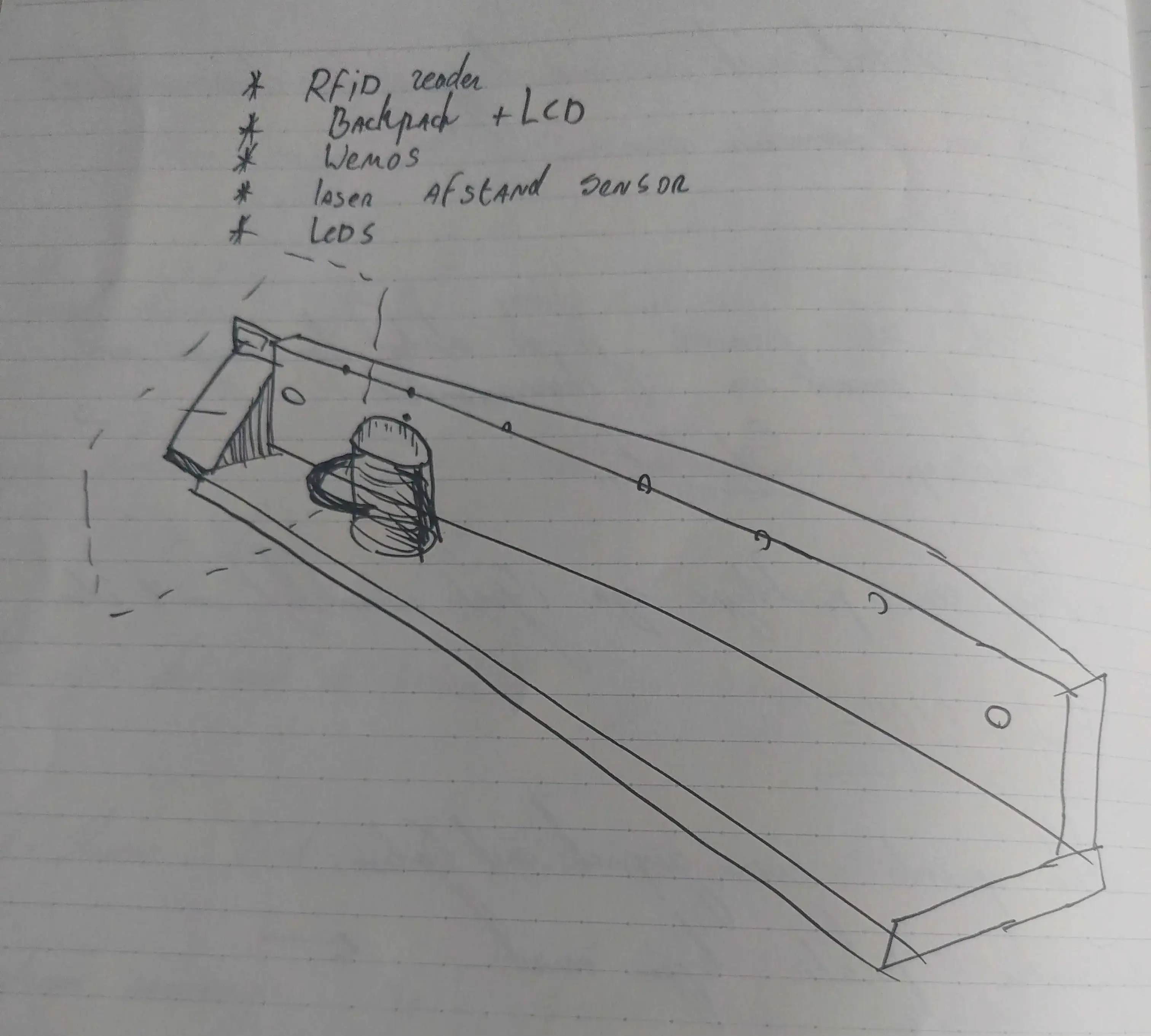
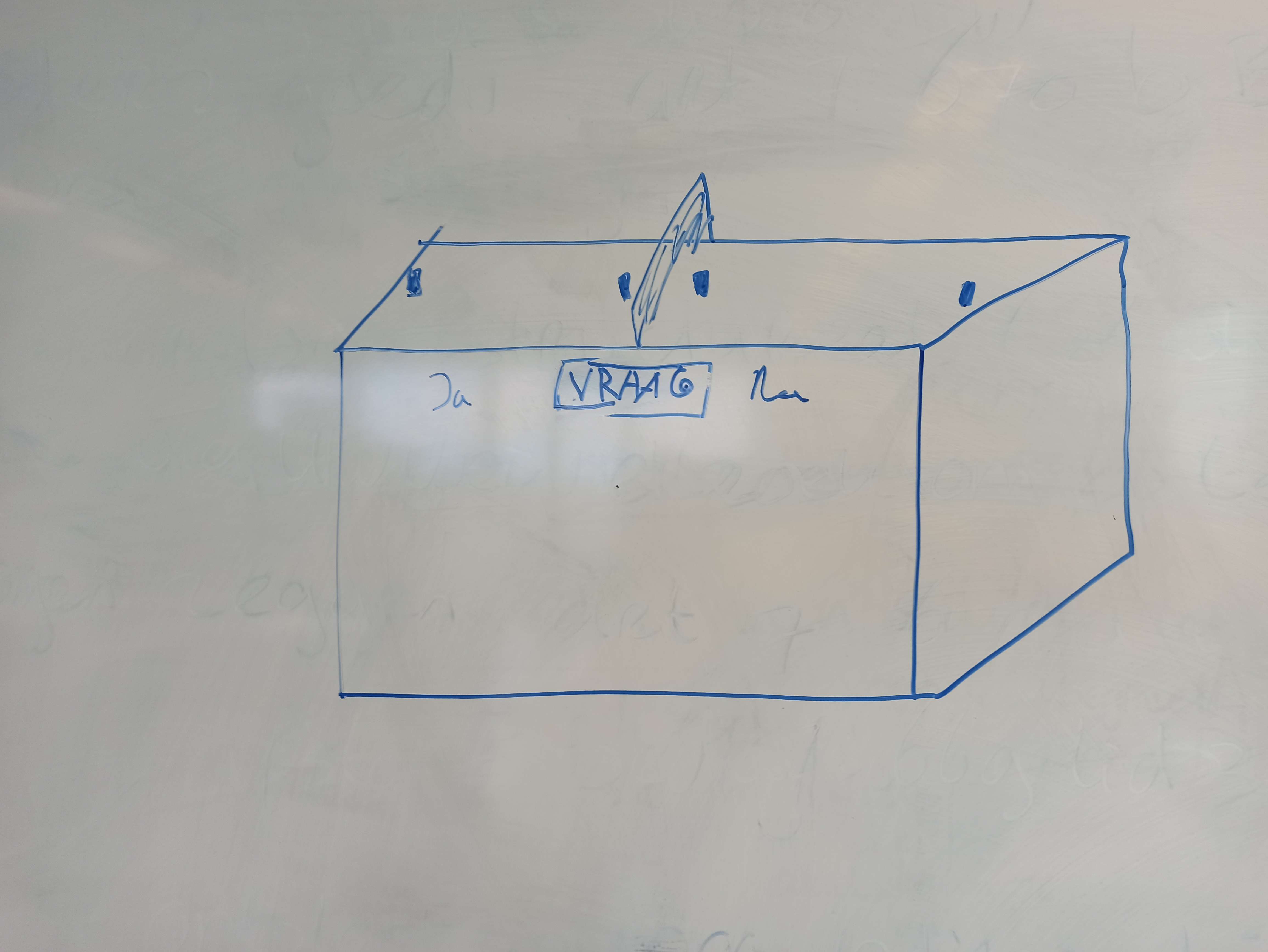
First design - The box
For the first design it has been decided to keep it really simple. It's going to be a simple cardboard structure with 2 cups above it and sensors between. The screen itself will be facing the user at an angle. This will display messages / tips about sustainability when a cup is taken and returned.
Sprint 2
Minimum Viable Product
Date: 22-05-2024
This document will contain the main priority goals of Sprint 2. These are additions to the goals set in the previous sprint.
1.0 Embedded Device
- Must be able to read laser sensors (is there a cup?)
- When sensor detects change, data should be sent, corresponding ledstrip color turns on.
- When sensor detects change, turn on separate led for small moment so one can see the sensor works.
- Sound is played when sensor detects change.
- Documentation on module, hardware & software
2.0 Website
- Keeps data on what users voted for (yes or no, including time of vote & corresponding question)
- Admins should be able to enter own questions linked to an SDG.
- Must be able to view and select all SDG’s and questions around them.
- Shows data in bar or pie-chart on current question.
- How many voted yes or no.
- Must be able to display ‘questions’ on separate tablet screen (separate page with question and current SDG).
- Documentation on module, software
3.0 Physical product
Wemos powered via USB adapter.
Wiring is hidden away.
- Must have sign with Multicolor LED strip.
- Sign also contains QR code for the user website to see statistics.
- Top of the device should have a red square and a green square.
- Should contain a hole where cup could be dropped in.
- These holes should contain the laser sensors to detect the cup passing through.
- Front of device should contain area to place current SDG.
- Font of device should contain screen to display current question.
- Documentation of the structure (contains explanations for construction and connection of the electronics. Additionally, future recommendations are included here)
Concepts
After our sprint review from Sprint 1, we have altered our concept. The main point of feedback of the client was that the device was a bit unclear to use, and that the screen was too small. We also got the impression that the interaction with the user could be improved, therefore we have drastically changed our concept.
Question answer machine
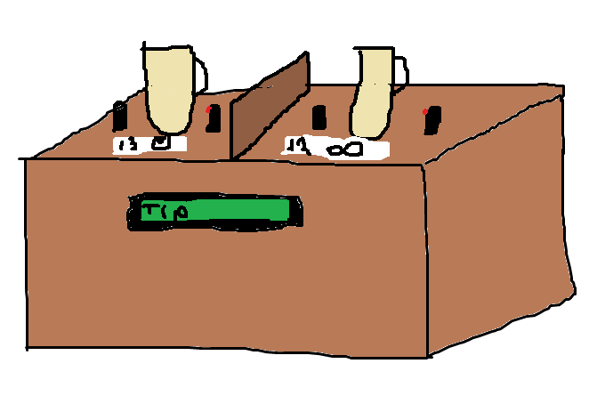
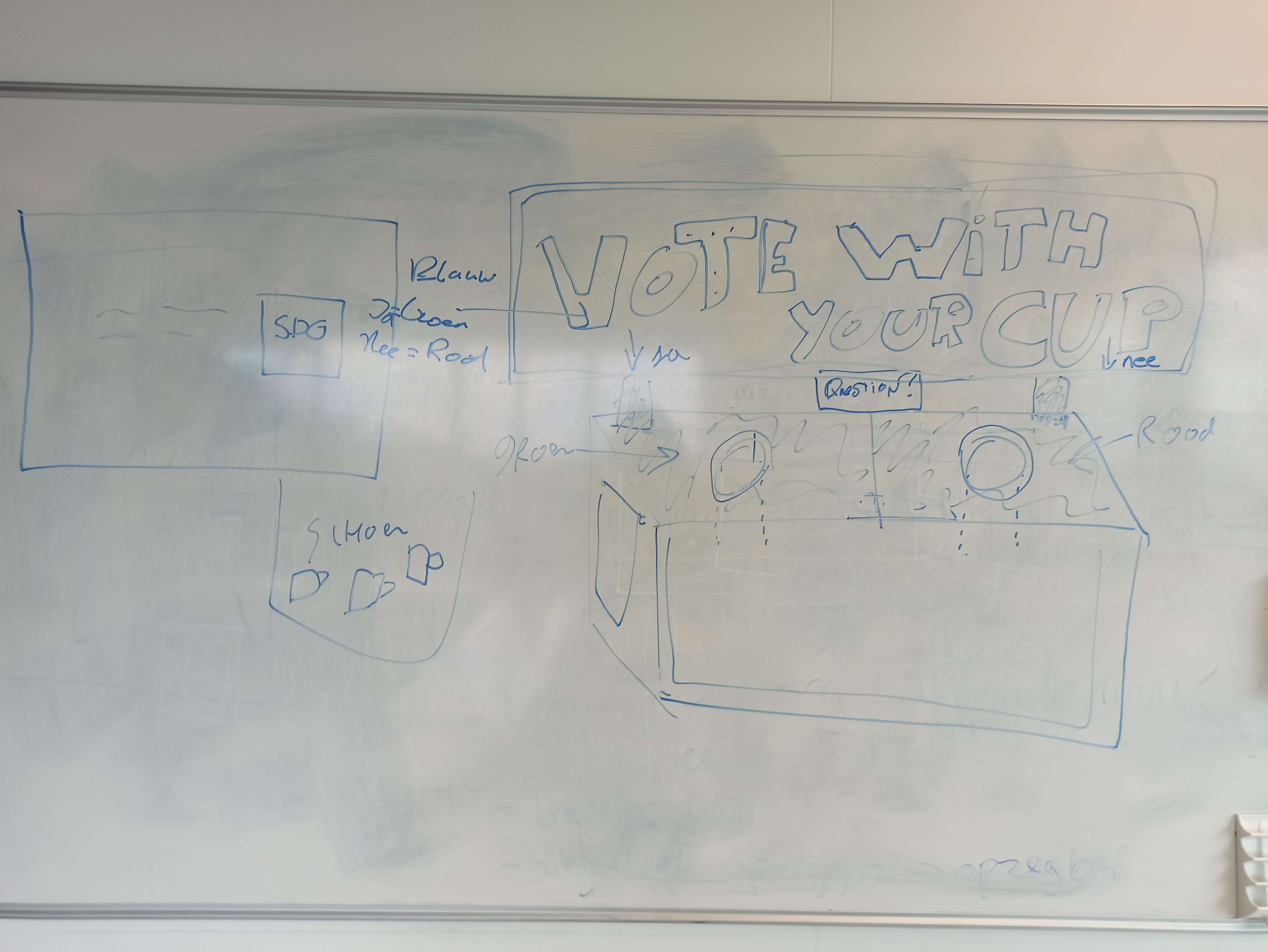
We have changed the idea to include two holes, one for YES and the other for NO. This is instead of the individual cup tracking, which we have ditched, since it was not that important for the client.
The device will have a large bin with clean cups. When the user returns to the device, they are prompted with a question, displayed on a big screen. They have to answer YES/NO to this question by returning the cup in the specific hole for YES and NO. It will also include a big sign with what the user must do, so there is no doubt in how to use the device.
This concept will track the answers of users on the specific question, and the administrator can determine the question which is displayed.
Additional features is the linking of questions to specific SDG's, the display of tips/facts for this SDG and a meter on the device to track how users have responded.
Modelled concept
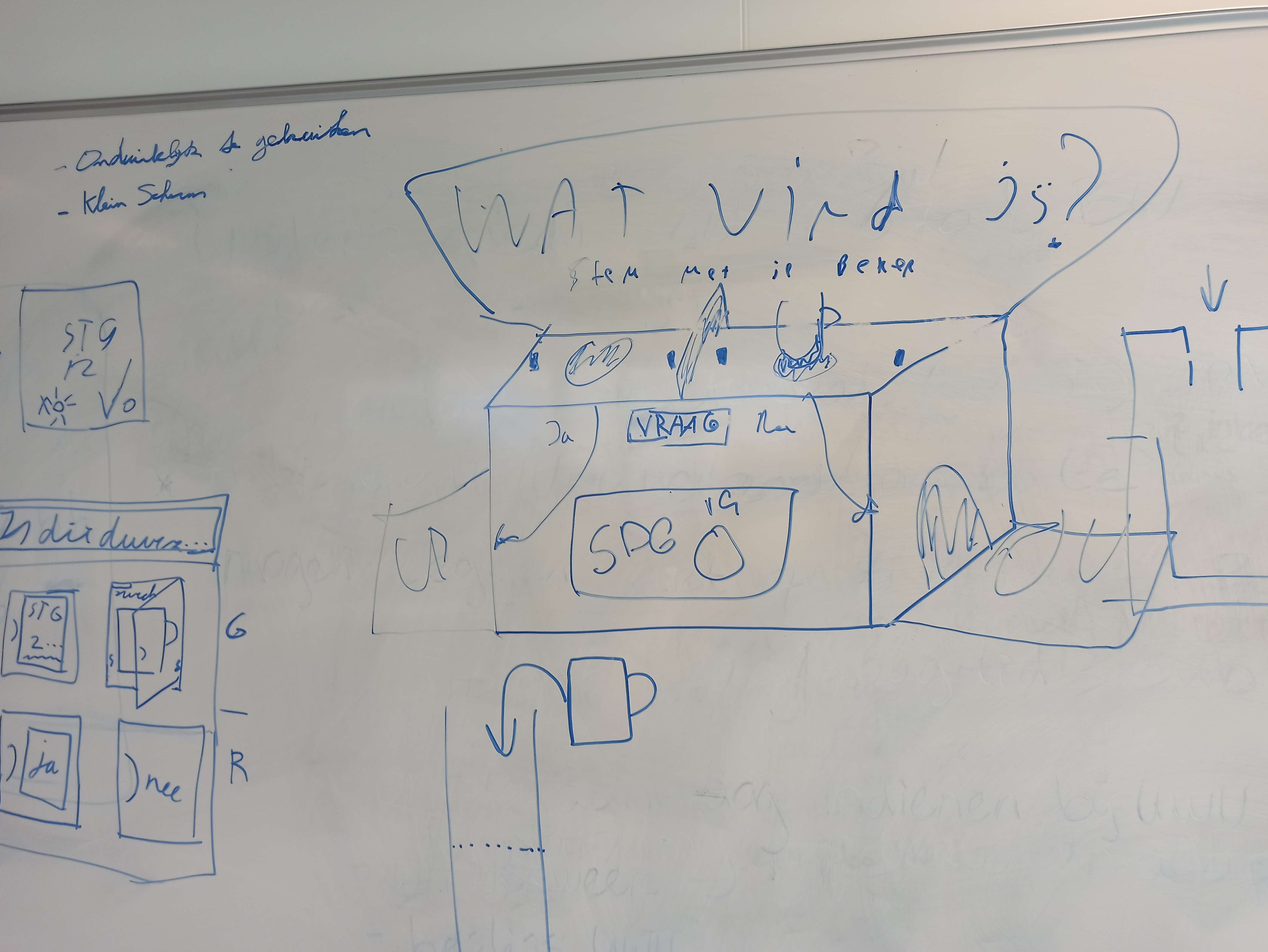
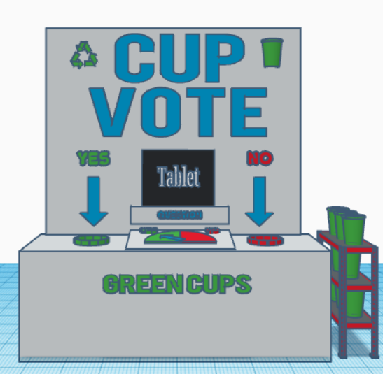
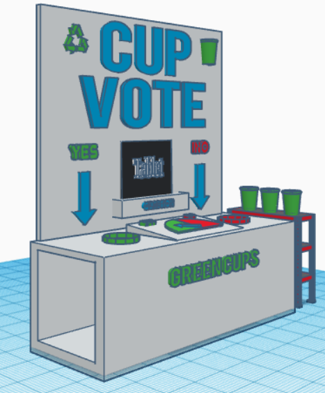
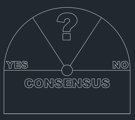
The important elements that the device need to have concluded from the meetings with the stakeholder, are that the device needs to attract the attention of the user and needs to be interactive/fun to use. The device also needs to be clear in a way that the user can instantly use the device without needing assistance or an explanation on the use of the device. To achieve these elements we are going to make a huge board with led letters to attract the attention of the user. The board will have have the text cup vote on it to show what the use is of the device. To make it even more clear we add two arrows on each side with the text yes and no the show the options for the user from which he or she can use to dispose the cup.
The middle/ bottom part will hold the tablet to showcase the sustainability goals set by the admin. This to show the user the topic in a clear way to start interacting with the device. To make it clear that the tablet has a function we add the text question on the border of the stand where the tablet is placed on to show the use of the tablet.
To make the design more fun to use we are planning to place led lights in the letters and around the holes were the cups will be placed in that will light up when it detects interaction. It also shows the amount of yes and no chosen by the user through a moving arrow that indicates the answer chosen most, making it fun to see which answer is given most on the specific topic.
The box where the cups fall through needs to be clear on how to use and easy to clean and maintain. That is why we created a box with two holes on top one for the yes and one for the no answer. The box has for now to sides open to slide the box to catch the cups easily in and out to make it easy to clean or replace the box.
The design came out looking like the following:

Design
3D letters
We want to have letters that stand out, so we have designed one letter, to be able to test the concept.
To design the first design of the letter V, we need to take some details into consideration. The letter V needs to be big enough to house the led light in it, also the size needs to be big enough to attract the attention of the user. The material needs to bee see through for the LED-lights to have the effect that we want.
To achieve these goals, we have used the program Tinkercad to create the design. The size chosen for the first print of the letter is 13.5 cm horziontal 15 cm long, and 1 cm deep. Leaving hopefully enough space for the led lights to be put in it and big enough to grab the attention of the user. The material that is chosen to use is a transparent PLA, making it see though for the LED-lights to shine through it.
The design made to start the first print run looks like the following: 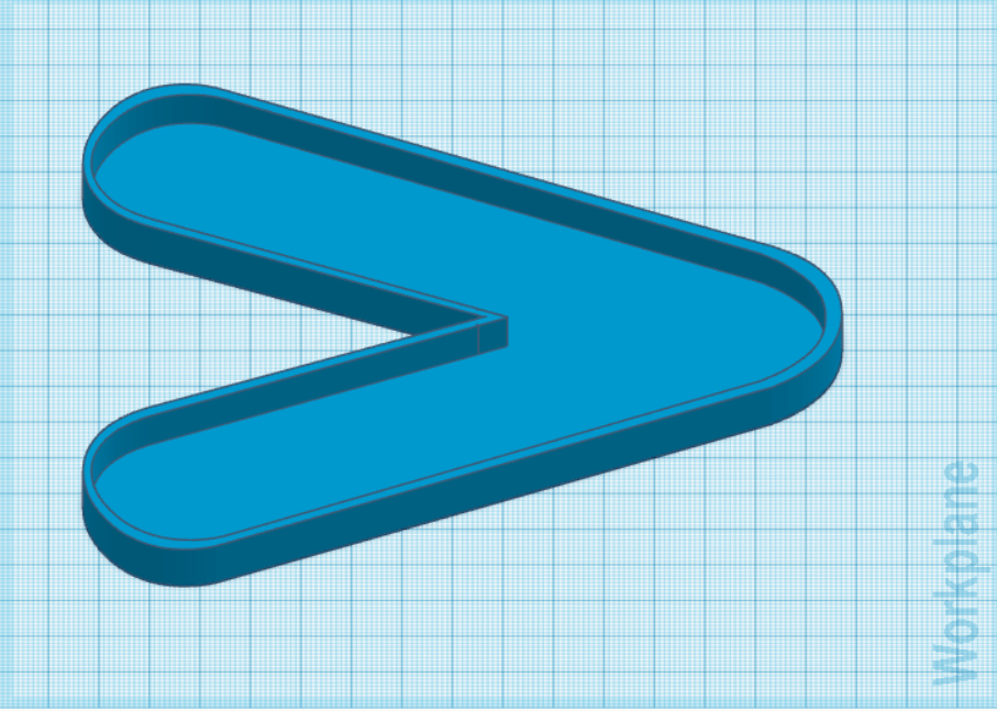
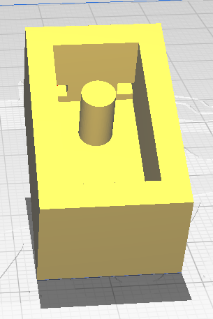
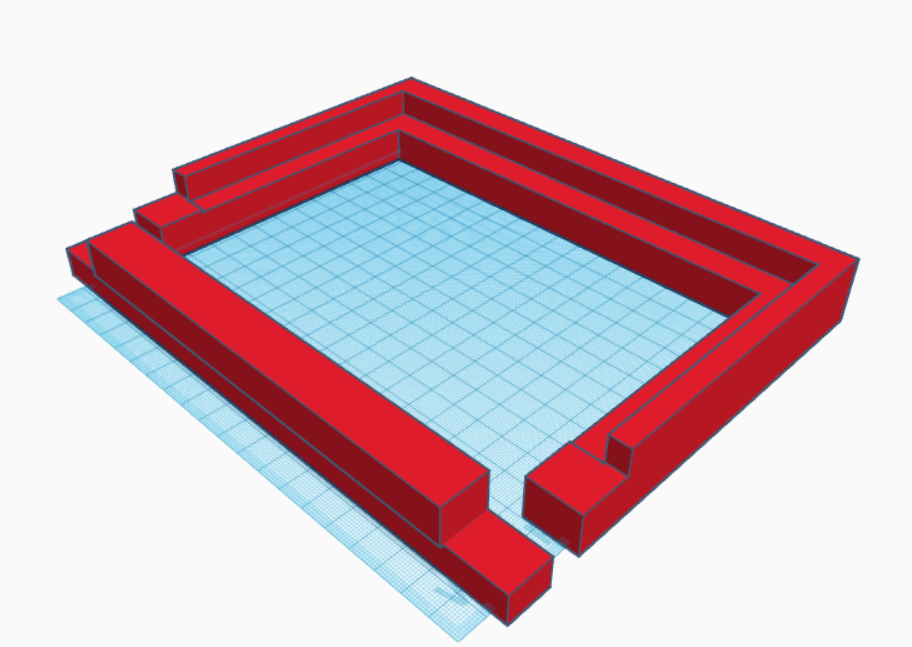
Box
Another part of the product is the design for the box frame. This is the part where the user will be able to drop cups into. To design this piece, we have made use of Autodesk Fusion. In this program we could make a 3D model, and then export the sketches from each side to a 2D format, so it could be used for the laser cutter.
Board
The device needed a sign to make the product stand out and offer clarity in it's use. The design is a simple square with the words CUP VOTE.

Sprint 3
Minimum Viable Product
These are additions to be made to the previous product, during the third sprint.
Embedded device
- Get new servo which works with current hardware.
- Update answer vector when a new question is selected.
- Polling for new selected question
2.0 Website
- Pie chart for selected questions answers
- Show answers of selected question in weekly chart, with time of vote.
- Must be able to run faster (Perhaps external server)
3.0 Physical design
Make tray for used cups.
Contains plexiglass or 3D printed letters, to diffuse LED light.
Sign contains indication for YES/NO.
Sign contains cut out for tablet.
Make frame for YES/NO meter.
Make place for embedded device
Concept
For the final sprint we have stuck to the concept which we defined in Sprint 2, since the client seemed to be happy with the concept. He wanted that concept to be improved and optimized.
Design
IR-sensor mounts
To properly attach the IR Beam-break sensors, we had to design some brackets which can hold them. This includes some holes for the cables to go through.
YES/NO Meter
In the previous sprint we have made a cardboard example of the YES/NO meter. For this sprint it had to be worked out and improved. It consist of multiple parts:
- Frame
- Half circle background
- Servo bracket
Frame
We opted to place the frame in the middle of the device. This will also give us space to place the hardware underneath it.
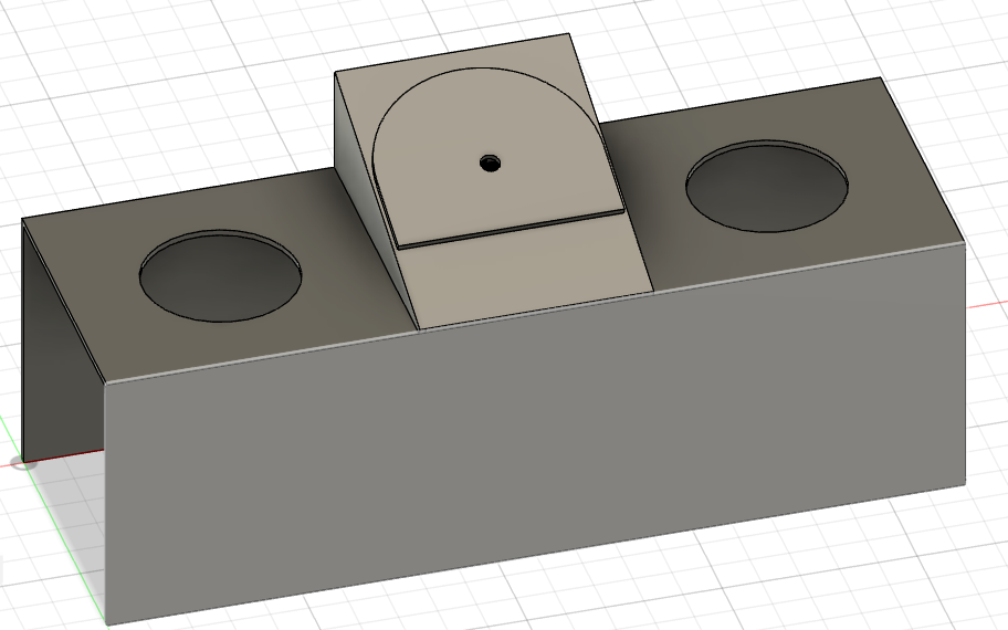
This will consist of two side plates and one top/cover plate. Above this another half-circle will be placed with the actual meter.
Half circle
The design of the half circle will include some text to make it more interesting and clear what it stands for. This text will be engraved into the half circle.
Servo bracket
Lastly we will need to have a bracket which is used to mount the servo to the casing. For this we designed a simple bracket in which the servo can be mounted.
YES/NO Sign
To make it clear to the user which hole in the box means what we need to indicate the holes by the word 'Yes' and the word 'No'. To indicate this correctly to the user we are going to place two wooden boards of each having a size of 10cm length and 10cm width. On these two boards the words yes and no are going to be engraved through the use of laser cutting. the size of the words are going to be 5 cm in length and 8.5 cm in width. The font chosen for the words is called Nefida Regular. These two boards will be placed onto the main headboard leaving enough space for the tablet and the arrows to be placed. The design of these words look like the following:
The words yes and no for on the headboard: 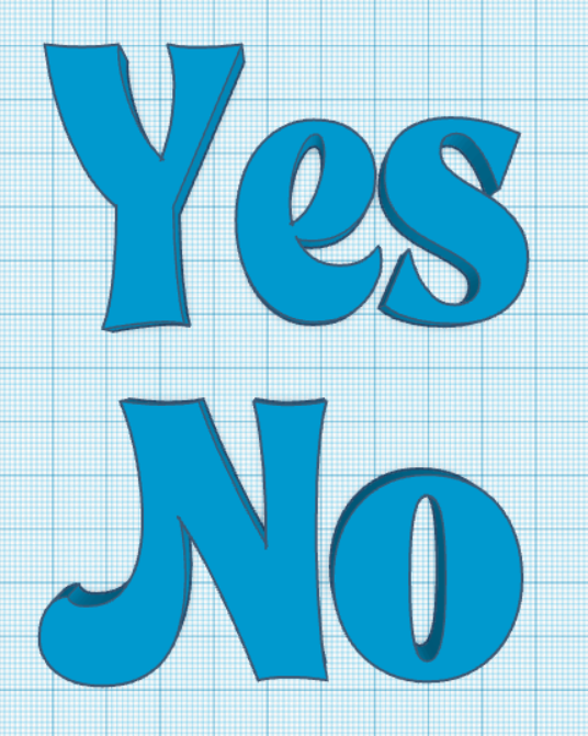
Arrow
To make it even more clear to the user on how to use the device we are going to add arrows underneath the yes and no for on the headboard. These arrows will also be engraved onto the wooden plate. To make the design for the arrow, Tinkercad is used. The arrow has a length of 10 cm and a width of 3 cm. The design looks like the following:
The arrow design for on the headboard: 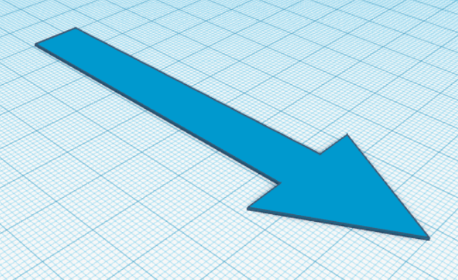
Light diffusion panel
Instead of printing individual letters, we have opted to add a plexiglass panel behind the letters, to diffuse the light, since it was not possible to print every letter individually.
Shown below is the cutout we designed, this is supposed to "wrap" around the current led strip mounted on the back of the sign, thus giving a nice glow to the product.

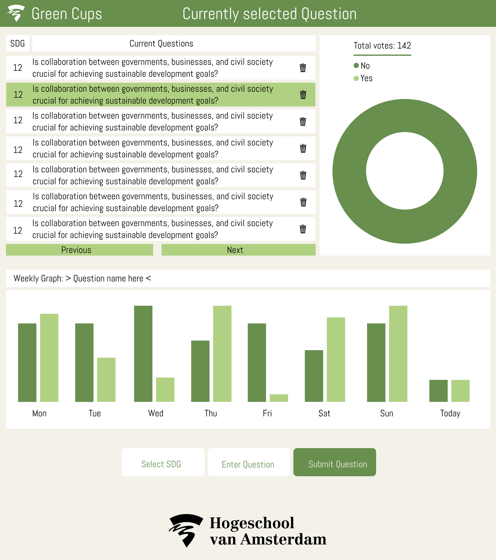
Website redesign
The website in it's current state looks fairly simple, therefore a new layout is designed to give priority to the information the user wants to see when starting the website. Below is a concept of the new website.
Tablet frame
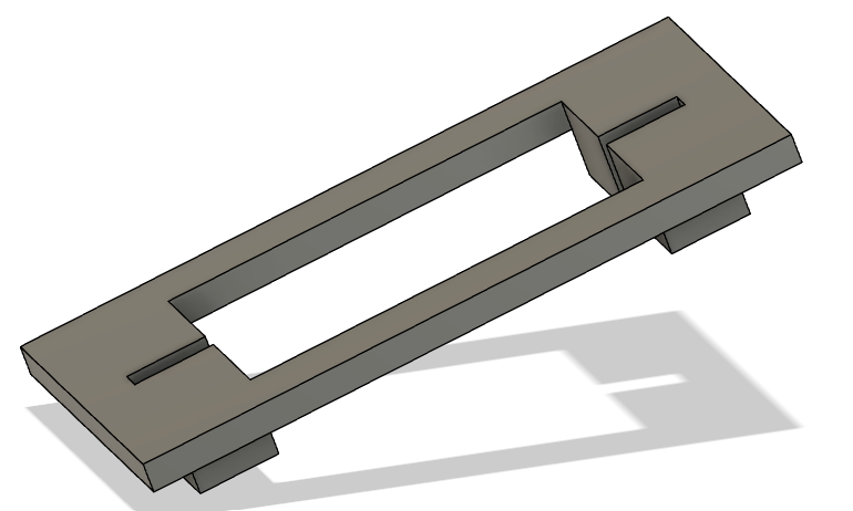
To show the question to the user we are using a tablet. To make it more readable for the user we are going to place the tablet onto the headboard to get it on eye height for the users. To do this we need to design a frame for the tablet to be placed in. It is important that the frame is strong enough to hold up the tablet. Also the tablet needs to be able to slide in and out of the frame for charging purpose while also hold the tablet secure making it not fallout of the frame.
To create this we figured that using the 3D printer would allow us to create the perfect design for the frame. Tinkercad was used for creating the following design:
The sizing of the tablet holder is as follows: It has a width of 14.5 centimeter, a length of 21.5 centimeter and a height of 2.5 centimeter.